After the trouble has been isolated to one of the feedback loops, troubleshooting can proceed as described in Tables A- 4,
Series Regulating Feedback Loop. When troubleshooting the series regulating loop, it is useful to open the loop since measurements made anywhere within a closed loop may appear abnormal. With a loop closed, it is very difficult to sep- arate cause from effect. As described in Tables
1.Shorting the emitter to collector of a transistor simu- lates saturation, or the full ON condition.
2.Shorting the emitter to base of a transistor cuts it off, and simulates an open circuit between emitter and collector.
Although a logical first choice might be to break the loop somewhere near its
series regulator backwards a stage at a time, since loop fail- ures occur more often at the higher power levels.
Preregulator Feedback Loop. The preregulator feedback loop (SCR control circuit) can be conveniently checked using Table
Overvoltage Protection Circuit Troubles
When troubleshooting the overvoltage protection circuit, it is useful to check the
Table
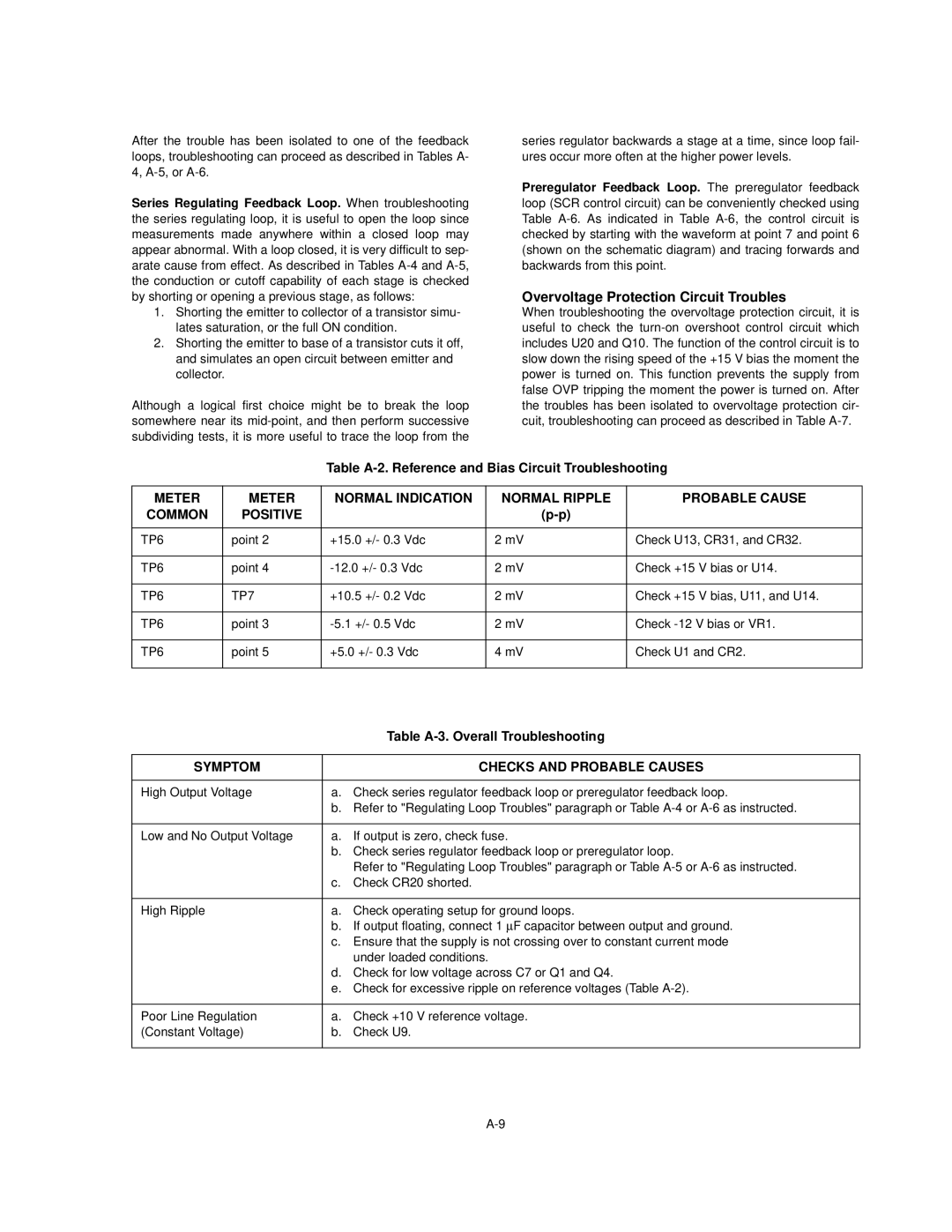
METER | METER | NORMAL INDICATION | NORMAL RIPPLE | PROBABLE CAUSE | |
COMMON | POSITIVE |
|
|
| |
|
|
|
|
| |
TP6 | point 2 | +15.0 +/- 0.3 Vdc | 2 mV | Check U13, CR31, and CR32. | |
|
|
|
|
|
|
TP6 | point 4 | 2 mV | Check +15 | V bias or U14. | |
|
|
|
|
|
|
TP6 | TP7 | +10.5 +/- 0.2 Vdc | 2 mV | Check +15 | V bias, U11, and U14. |
|
|
|
|
| |
TP6 | point 3 | 2 mV | Check | ||
|
|
|
|
| |
TP6 | point 5 | +5.0 +/- 0.3 Vdc | 4 mV | Check U1 and CR2. | |
|
|
|
|
|
|
|
| Table |
|
|
|
SYMPTOM |
| CHECKS AND PROBABLE CAUSES |
|
|
|
High Output Voltage | a. | Check series regulator feedback loop or preregulator feedback loop. |
| b. Refer to "Regulating Loop Troubles" paragraph or Table | |
|
|
|
Low and No Output Voltage | a. | If output is zero, check fuse. |
| b. Check series regulator feedback loop or preregulator loop. | |
|
| Refer to "Regulating Loop Troubles" paragraph or Table |
| c. | Check CR20 shorted. |
|
|
|
High Ripple | a. | Check operating setup for ground loops. |
| b. If output floating, connect 1 μF capacitor between output and ground. | |
| c. Ensure that the supply is not crossing over to constant current mode | |
|
| under loaded conditions. |
| d. Check for low voltage across C7 or Q1 and Q4. | |
| e. Check for excessive ripple on reference voltages (Table | |
|
|
|
Poor Line Regulation | a. | Check +10 V reference voltage. |
(Constant Voltage) | b. | Check U9. |
|
|
|