AUTO-SERIES OPERATION
Mixed model numbers may be employed in
Total output voltage to ground must not exceed 240 Vdc.
Determining Resistors. External resistors control the fraction (or multiple) of the master unit's voltage setting that is supplied from the slave unit. Notice that the percentage of the total output volt- age contributed by each supply is independent of the magnitude of the total voltage. For two units in
(R1+R2)/R1 | = (Vo/Vm) |
R2/R1 | = (Vs/Vm) |
Where Vo | = |
Vm | = master unit's output voltage |
Vs | = slave unit's output voltage |
For example, using the E3617A as a slave unit and putting R2=50 kΩ (1/4 watt), then from the above equations,
R1 = R2(Vm/Vs) = 50(Vm/Vs) kΩ
In order to maintain the temperature coefficient and stability perfor- mance of the supply, choose stable, low noise resistors.
It is recommended to connect a 0.1 μF capacitor in paral- lel with R2 in two supplies operation or R2 and R4 in three supplies operation to ensure the stable operation.
Setting Voltage and Current. Use the master unit's controls to set the desired output voltage and current. The VOLTAGE control of the slave unit is disabled. Turning the voltage control of the master unit will result in a continuous variation of the output of the series combination, with the contribution of the master's output voltage to that of the slave's voltage always remaining in the ratio of the external resistors. Set the CURRENT control of slave unit
above the master unit's current setting to avoid having the slave switch to CC operation.
When in CC operation the combined output current is the same as the master unit's current setting, and when in CV operation the combined output voltage is the sum of the master unit's and the slave unit's output voltages.
Overvoltage Protection. Set the OVP shutdown voltage in each unit so that it shuts down at a voltage higher than its output voltage during
MASTER POWER SUPPLY |
|
|
|
|
|
|
|
|
|
| |||
MASTER |
| LOCAL |
| + | _ |
| + | _ | + | _ |
|
| |
M/S 1 | M/S 2 | CV | CC | SENSE | +S | OUT | CV |
| CC | VREF A1 A2 A3 | A4 A5 | ||
SLAVE |
| REMOTE |
|
| |||||||||
|
|
|
|
|
|
|
|
|
|
| |||
|
|
|
|
| LOAD |
|
|
|
|
|
|
|
|
|
|
|
|
|
|
|
|
|
|
| R1 | R2 |
|
SLAVE POWER SUPPLY |
|
|
|
|
|
|
|
|
|
|
| ||
MASTER |
| LOCAL |
| + | _ |
| + | _ | + | _ |
|
| |
M/S 1 | M/S 2 | CV | CC | SENSE | +S | OUT | CV |
| CC | VREF A1 A2 A3 | A4 A5 | ||
SLAVE |
| REMOTE |
|
| |||||||||
|
|
|
|
|
|
|
|
|
|
| |||
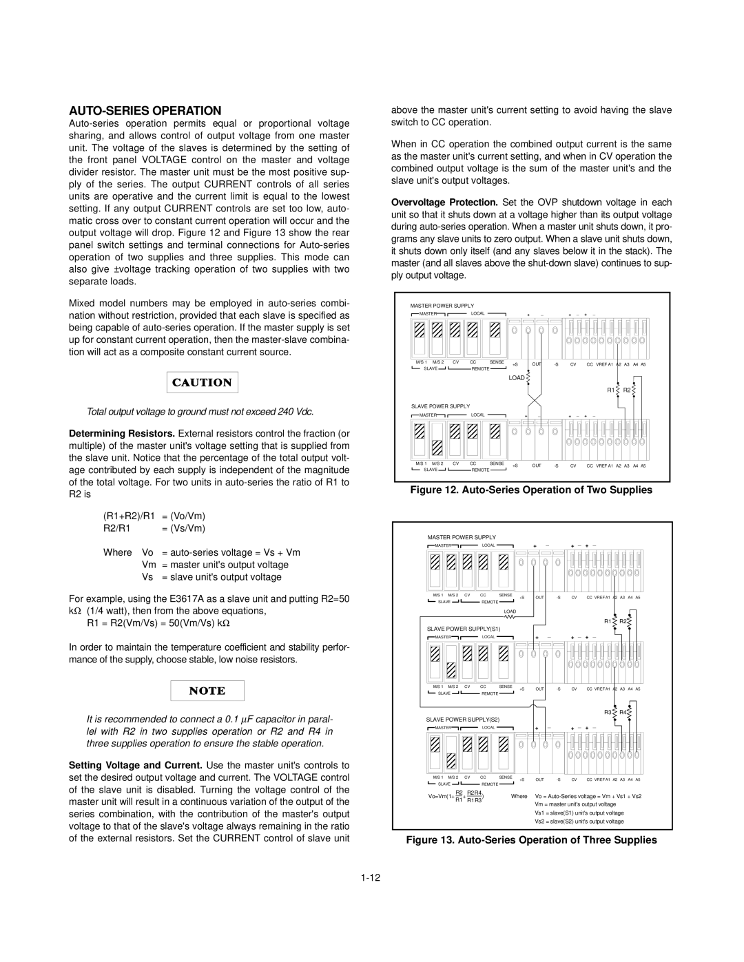
Figure 12. Auto-Series Operation of Two Supplies
MASTER POWER SUPPLY |
|
|
| _ |
| _ | + _ |
|
|
| ||
MASTER |
| LOCAL |
|
| + | + |
|
|
| |||
M/S 1 M/S 2 | CV | CC | SENSE | +S | OUT | CV |
| CC VREF A1 A2 | A3 | A4 | A5 | |
SLAVE |
|
|
|
| ||||||||
| REMOTE |
|
|
|
|
|
|
|
|
|
| |
|
|
| LOAD |
|
|
|
|
|
|
|
|
|
|
|
|
|
|
|
|
|
| R1 | R2 |
|
|
SLAVE POWER SUPPLY(S1) |
|
| _ |
| _ | + _ |
|
|
| |||
MASTER |
| LOCAL |
|
| + | + |
|
|
| |||
M/S 1 M/S 2 | CV | CC | SENSE | +S | OUT | CV |
| CC VREF A1 A2 | A3 | A4 | A5 | |
SLAVE |
|
|
|
| ||||||||
| REMOTE |
|
|
|
|
|
|
|
|
|
| |
|
|
|
|
|
|
|
|
| R3 | R4 |
|
|
SLAVE POWER SUPPLY(S2) |
|
| _ |
| _ | + _ |
|
|
| |||
MASTER |
| LOCAL |
|
| + | + |
|
|
| |||
M/S 1 M/S 2 | CV | CC | SENSE | +S | OUT | CV |
| CC VREF A1 A2 | A3 | A4 | A5 | |
SLAVE |
|
|
|
| ||||||||
| REMOTE |
|
|
|
|
|
|
|
|
|
| |
Vo=Vm(1+ R2+ R2R4) | Where | Vo = | ||||||||||
R1 | R1R3 |
|
| Vm = master unit's output voltage |
|
|
| |||||
|
|
|
|
|
|
|
| |||||
|
|
|
|
| Vs1 = slave(S1) unit's output voltage |
|
| |||||
|
|
|
|
| Vs2 = slave(S2) unit's output voltage |
|
| |||||