e.Record output voltage across Rs and convert it to current by dividing this voltage by Rs.
f.Adjust autotransformer to the high line voltage (127 Vac for nominal 115 Vac, 110 Vac for nominal 100 Vac, and 253 Vac for nominal 230 Vac).
g.When the reading settles, record the voltage across Rs again and convert it current. Check that the two
recorded readings differ less than 0.01% of output current plus 250 μA.
PARD(Ripple and Noise)
Definition : The residual ac current which is superimposed on the dc output current of a power supply. Constant current PARD is specified as the
PARD(RMS) Measurement
Test Parameter:
Measured Variable: Output Current(rms)
Expected Results: E3614A: Less than 5 mA rms E3615A: Less than 2 mA rms E3616A: Less than 500 μA rms E3617A: Less than 500 μA rms
Test Procedure:
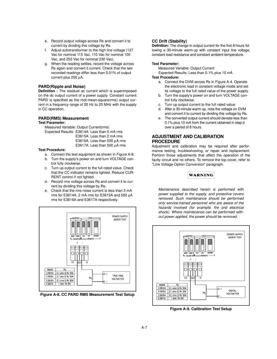
a.Connect the test equipment as shown in Figure
b.Turn the supply's power on and turn VOLTAGE con- trol fully clockwise.
c.Turn up output current to the full rated value. Check that the CC indicator remains lighted. Reduce CUR- RENT control if not lighted.
d.Record rms voltage across Rs and convert it to cur- rent by dividing this voltage by Rs.
e.Check that the rms noise current is less than 5 mA rms for E3614A, 2 mA rms for E3615A and 500 μA rms for E3616A and E3617A respectively.
Figure A-8. CC PARD RMS Measurement Test Setup
CC Drift (Stability)
Definition: The change in output current for the first 8 hours fol- lowing a
Test Parameter:
Measured Variable: Output Current
Expected Results: Less than 0.1% plus 10 mA
Test Procedure:
a.Connect the DVM across Rs in Figure
b.Turn the supply's power on and turn VOLTAGE con- trol fully clockwise.
c.Turn up output current to the full rated value.
d.After a
e.The converted output current should deviate less than 0.1% plus 10 mA from the current obtained in step d over a period of 8 hours.
ADJUSTMENT AND CALIBRATION
PROCEDURE
Adjustment and calibration may be required after perfor- mance testing, troubleshooting, or repair and replacement. Perform those adjustments that affect the operation of the faulty circuit and no others. To remove the top cover, refer to "Line Voltage Option Conversion" paragraph.
Maintenance described herein is performed with power supplied to the supply, and protective covers removed. Such maintenance should be performed only
