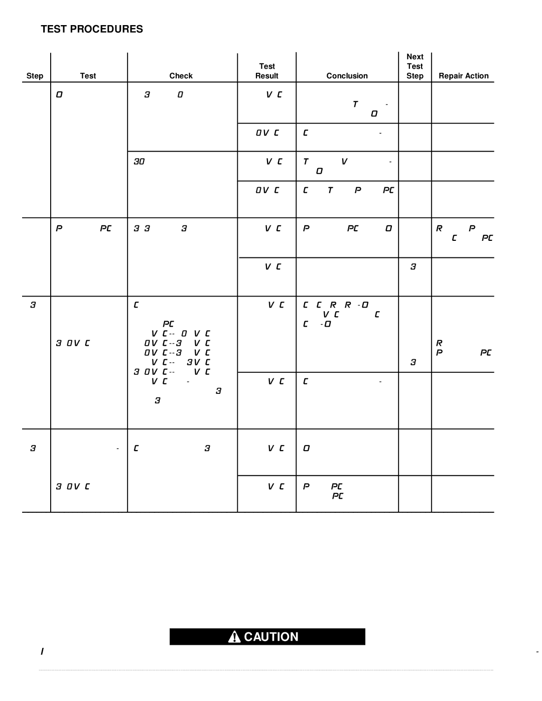
TEST PROCEDURES
|
|
|
|
|
| Next |
|
|
|
|
| Test |
| Test |
|
Step | Test | Check |
| Result | Conclusion | Step | Repair Action |
|
|
|
|
|
|
|
|
1A | Output pilot circuit | 223A to 210 |
| 24 VAC | Fan thermostat, choke | 1B |
|
| (set S4 on) |
|
|
| thermostat, T1 trans- |
|
|
|
|
|
|
| former and S4 all OK. |
|
|
|
|
|
|
|
|
|
|
|
|
|
| 0 VAC | Check above compo- |
|
|
|
|
|
|
| nents. |
|
|
|
|
|
|
|
|
|
|
1B |
| 302 (pos) to 275D (neg) |
| 15 VDC | T1 and 15V power sup- | 2 |
|
|
|
|
|
| ply OK. |
|
|
|
|
|
|
|
|
|
|
|
|
|
| 0 VDC | Check T1 and Power PC |
|
|
|
|
|
|
| Board. |
|
|
|
|
|
|
|
|
|
|
2 | Protection PC | 313 (neg) to 311 (pos) |
| <1 VDC | Protection PC Board OK |
| Replace Power |
| board output (set |
|
|
|
|
| and Control PC |
| S4 on) |
|
|
|
|
| Boards |
|
|
|
|
|
|
|
|
|
|
|
| >5 VDC |
| 3A |
|
|
|
|
|
|
|
|
|
3A | Static capacitor | Compare voltage across |
| <25 VDC | C1, C2, R1, R9 - OK |
|
|
| balance (set S4 | terminals 9 & 12 of each |
| difference | (575 VAC machine C14, |
|
|
| off) | Switch PC Board. |
| between | C15 - OK) |
|
|
|
| 575 VAC |
| readings |
|
|
|
| 380 VAC input | 460 VAC |
|
|
|
| Replace |
| and higher test | 440 VAC |
|
|
|
| Protection PC |
|
| 415 VAC |
|
|
| 3B | Board |
|
| 380 VAC |
|
|
|
|
|
|
|
|
|
|
|
| |
|
| 575 VAC only - compare |
| >25 VDC | Check above compo- |
|
|
|
| voltage across 9A & 13 |
| difference | nents. |
|
|
|
| and 13 & 12A; then, 9B & |
|
|
|
|
|
|
| 15 and 15 & 12B |
|
|
|
|
|
|
|
|
|
|
|
|
|
3B | Dynamic capaci- | Connect as in step 3A. |
| <25 VDC | OK |
|
|
| tor balance (set | Same voltages as above. |
|
|
|
|
|
| S4 on) |
|
|
|
|
|
|
|
|
|
|
|
|
|
|
| 380 VAC input |
|
| >25 VDC | Power PC Board or | 4 |
|
| and higher test |
|
|
| Switch PC Boards are | and |
|
|
|
|
|
| damaged. | 5 |
|
|
|
|
|
|
|
|
|
![]() CAUTION
CAUTION
If for any reason you do not understand the test procedures or are unable to perform the tests/repairs safely, con- tact your local Authorized Field Service Facility for technical troubleshooting assistance before you proceed.
– 16 – | – |