ASPIRATEUR HAUTE PERFORMANCE
ASPIRADORA DE ALTO RENDIMIENTO
Models 5621 and Modèles 5621 et Modelos 5621 y
SELF PROPELLED
Table of Contents Important Information
A. Safety Decals
WARNINGDANGER IMPROPER USE OR CARE OF THIS HIGH
PERFORMANCE VAC, OR FAILURE TO WEAR PROPER
PROTECTION CAN RESULT IN SERIOUS INJURY
Safety and Warnings
P/N Warning Label P/N P/N Warning Label
A. Warnings - Don’ts
B. Warnings - Do’s
WARNING DANGER
WARNING DANGER
B. Warnings - Do’s Continued
C. Engine/ Fuel Warnings - Don’ts
D. Engine/ Fuel Warnings - Do’s
WARNING DANGER
A. Assembly
5.Attach nozzle assembly to base unit
seal strap
WARNING DANGER
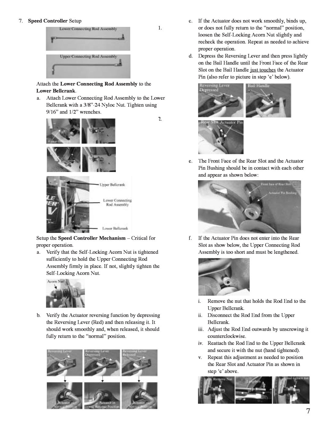
7.Speed Controller Setup
HANDLE FUEL WITH CARE. IT IS HIGHLY
B.Put Oil and Gasoline in Engine Before Starting
WARNING DANGER
DO NOT USE OR SERVICE THE UNIT WHEN IT’S
C. Use of Lifting Lug
A. Starting Instructions
B. Self-PropelledInstructions
C. Vacuuming
D. Empty Debris Bag
E. Refueling the Engine
WARNING DANGER
B. Maintenance
A. Storage
Area
Every
DISCONNECT THE SPARK PLUG WIRES BEFORE
ANY CLEANING OR MAINTENANCE WARNING DANGER
C. Removing Blockage in Moving Parts
E. Changing V-Belt
HPV Parts Assembly
CONNECT TO ENGINE 58THROTTLE LEVER
HPV Parts List
DESCRIPTION
8 4x 5 7 3
DESCRIPTION
DESCRIPTION
HPV Collector Assembly
KEY NO
KEY NO
PART NO
DESCRIPTION
KEY NO
LITTLE WONDER
1 YEAR LIMITED SERVICE & WARRANTY POLICY
FOR HIGH PERFORMANCE VAC
DIVISION OF SCHILLER-PFEIFFER,INCORPORATED
Table des matières Informations importantes
A. Décalcomanies de sécurité
AVERTISSEMENT DANGER
POUR ÉCARTER LES RISQUES DE BLESSURE GRAVE
UTILISER ET ENTRETENIR CET ASPIRATEUR DE FAÇON
N de référence
Décalcomanie d’avertissement
N de référence 600604 N de référence 600602
Décalcomanie d’avertissement
A. Avertissements – Ce qu’il ne faut pas faire
B. Avertissements – Ce qu’il faut faire
AVERTISSEMENT DANGER
AVERTISSEMENT DANGER
B.Advertencias – “Hacer siempre” – continuación
TÊTE D’ASPIRATION N’EST PAS INSTALLÉE
A. Assemblage
AVERTISSEMENT
DANGER
7.Réglage de la commande de vitesse
B.Plein d’huile et d’essence avant le démarrage
AVERTISSEMENT DANGER
C. Utilisation de l’oreille de levage
A. Instructions de démarrage
B. Instructions concernant le mode autotracté
AVERTISSEMENT DANGER
C. Passage de l’aspirateur
D. Vidage du sac à déchets
E. Remplissage du réservoir d’essence
AVERTISSEMENT DANGER
A. Rangement
B. Entretien
Domaine
À chaque
E. Remplacement de la courroie trapézoïdale
Nomenclature des assemblages HPV
THROTTLE LEVER
Nomenclature des pièces HPV
8 4x 5 7 3
REPÈRE
NO DE RÉF. DESCRIPTION
REPÈRE
NO DE RÉF. DESCRIPTION
Ensemble collecteur HPV
REPÈRE
Chemise HPV
Tête d’aspiration HPV
ENSEMBLE TÊTE D’ASPIRATION
NO DE RÉF. DESCRIPTION
LITTLE WONDER
GARANTIE POUR L’ASPIRATEUR HAUTE PERFORMANCE HPV
DIVISION OF SCHILLER-PFEIFFER,INCORPORATED
1028 STREET ROAD, P.O. BOX SOUTHAMPTON, PA
Índice de materias Información importante
A. Etiquetas engomadas de salvaguardias
ADVERTENCIA PELIGRO
LEA Y ENTIENDA TODAS LAS REGLAS PARA LA
OPERACIÓN SEGURA, ASÍ COMO TODAS LAS
Núm./Comp.
Etiqueta de advertencia
P/N Núm./Comp. Etiqueta de advertencia
ASPIRADORA DE ALTO RENDIMIENTO
A. Advertencias – “No hacer”
B. Advertencias – “Hacer siempre”
ADVERTENCIA PELIGRO
ADVERTENCIA PELIGRO
B.Advertencias – “Hacer siempre” – continuación
A. Ensamble
ADVERTENCIA
PELIGRO
NUNCA HAGA FUNCIONAR NI OPERE ESTA
7.Disposición del control de la velocidad
ADVERTENCIA PELIGRO
Extraiga la tuerca Acorte
Tuerca apretada con la fuerza de los dedos
Correcto - Recta
C. Uso del perno elevador
A. Instrucciones para su arranque
B. Instrucciones para la auto-propulsión
ADVERTENCIA PELIGRO
C. Aspirado
D. Vaciado de la bolsa para los desechos
E. Reabastecimiento de combustible al motor
ADVERTENCIA PELIGRO
A. Almacenamiento
B. Mantenimiento
Área
Cada vez
E. Cambio de la banda impulsora en
58 THROTTLE LEVER
Ensamble de los componentes de la aspiradora HPV
CONNECT TO ENGINE
Lista de componentes de la aspiradora HPV
8 4x 5 7 3
COMP. NÚM. DESCRIPCIÓN
CLAVE
COMP. NÚM. DESCRIPCIÓN
Ensamble del recolector de la aspiradora HPV
CLAVE
COMP. NÚM. DESCRIPCIÓN
CANT
ENSAMBLE DE LA TOLVA
COMP. NÚM. DESCRIPCIÓN
CANT
CLAVE
LITTLE WONDER
ASPIRADORAS HPV DE ALTO RENDIMIENTO
DIVISION OF SCHILLER-PFEIFFER,INCORPORATED
1028 STREET ROAD, P.O. BOX SOUTHAMPTON, PA
LITTLE WONDER
DIVISION OF SCHILLER-PFEIFFER,INCORPORATED
1028 STREET ROAD, P.O. BOX SOUTHAMPTON, PA
12/07