3 Troubleshooting

Combustion Analysis Procedure

1.Turn the main power off to the boiler by placing the “On/ Off” switch in the OFF position.

2.Remove the flue temperature sensor from the flue pipe connection. Note: Combustion measurements will be made at this point.

3.Turn the main power on to the boiler by placing the “On/Off” switch in the ON position.

4.Place the boiler into the active position by pressing the RIGHT SELECT [ON] key (see page 7).

5.Locate the pinhole button below the RESET button on the display board (see page 7). Insert a thin wire (such as a paper clip) into the hole and press the button once and hold for 5 seconds to place the boiler into Service Mode. In Service Mode the boiler will fire at ignition speed and will then modulate up to full fire.

6.Remove the flue temperature sensor. Insert the probe from a combustion analyzer into the hole left by the removal of the flue temperature sensor.

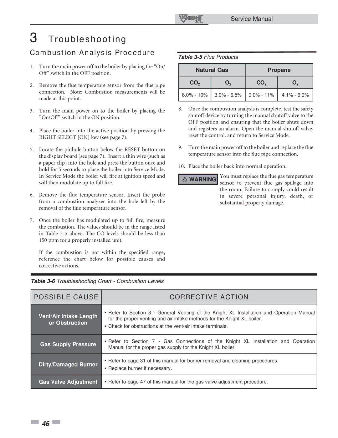
7.Once the boiler has modulated up to full fire, measure the combustion. The values should be in the range listed in Table 3-5 above. The CO levels should be less than 150 ppm for a properly installed unit.

If the combustion is not within the specified range, reference the chart below for possible causes and corrective actions.

Service Manual

Table 3-5Flue Products

Natural Gas

Propane


CO2

O2

CO2

O2

8.0% - 10%

3.0% - 6.5%

9.0% - 11%

4.1% - 6.9%


8.Once the combustion analysis is complete, test the safety shutoff device by turning the manual shutoff valve to the OFF position and ensuring that the boiler shuts down and registers an alarm. Open the manual shutoff valve, reset the control, and return to Service Mode.

9.Turn the main power off to the boiler and replace the flue temperature sensor into the flue pipe connection.

10.Place the boiler back into normal operation.

￿WARNING You must replace the flue gas temperature sensor to prevent flue gas spillage into

the room. Failure to comply could result in severe personal injury, death, or substantial property damage.

Table 3-6Troubleshooting Chart - Combustion Levels

POSSIBLE CAUSE

CORRECTIVE ACTION


Vent/Air Intake Length

• Refer to Section 3 - General Venting of the Knight XL Installation and Operation Manual

for the proper venting and air intake methods for the Knight XL boiler.

or Obstruction

• Check for obstructions at the vent/air intake terminals.


Gas Supply Pressure

• Refer to Section 7 - Gas Connections of the Knight XL Installation and Operation

Manual for the proper gas supply for the Knight XL boiler.


Dirty/Damaged Burner

• Refer to page 31 of this manual for burner removal and cleaning procedures.

• Replace burner if necessary.


Gas Valve Adjustment

• Refer to page 47 of this manual for the gas valve adjustment procedure.


46

Page 46
Image 46
Lochinvar 801, 400 service manual Combustion Analysis Procedure

400, 801 specifications

The Lochinvar 801,400 is a cutting-edge solution in the realm of high-efficiency commercial water heating. This model represents a significant advancement in the design and functionality of water heaters, catering primarily to the demands of large-scale facilities like hotels, hospitals, and large industrial operations.

One of the standout features of the Lochinvar 801,400 is its impressive heating capacity, which can produce up to 801,400 BTUs, making it suitable for high-demand applications. This output is crucial for establishments that require a consistent supply of hot water, such as commercial kitchens and laundry facilities. The robust design ensures that it can handle peak demand periods without compromising performance.

Another significant aspect is the innovative use of advanced technology in its operation. The Lochinvar 801,400 integrates smart controls that enhance its efficiency and ease of operation. These controls allow for precise monitoring and adjustment of water temperatures, ensuring that the system operates within optimal parameters while maximizing energy savings. The intelligent monitoring system can provide real-time updates, making it easier for facility managers to keep track of performance and address maintenance needs proactively.

The construction of the Lochinvar 801,400 incorporates durable materials that not only enhance the longevity of the unit but also offer resistance to corrosion and wear. This durability translates into lower maintenance costs and an extended lifespan for the unit, making it a worthwhile investment for businesses.

Moreover, the Lochinvar 801,400 is designed with energy efficiency in mind. It boasts a high thermal efficiency rating, which reduces operational costs and minimizes the carbon footprint of heating operations. This efficiency is critical in today’s environmentally conscious market, where businesses are seeking to reduce their energy consumption and comply with strict regulations.

The design of the Lochinvar 801,400 also prioritizes safety, featuring innovative safety controls and fail-safes that protect both the unit and the users.

In summary, the Lochinvar 801,400 offers a combination of high capacity, advanced technology, durability, and energy efficiency, making it an excellent choice for commercial water heating solutions. As industries continue to evolve, the demand for reliable and efficient water heating solutions like the Lochinvar 801,400 will only increase.