3 Troubleshooting (continued)

Gas valve adjustment procedure

If adjustment of the gas valve is deemed necessary, use the following procedures: (Note: The procedures below are model specific.)

CAUTION

Under normal operating conditions this

valve should not need adjusting.

Model 400

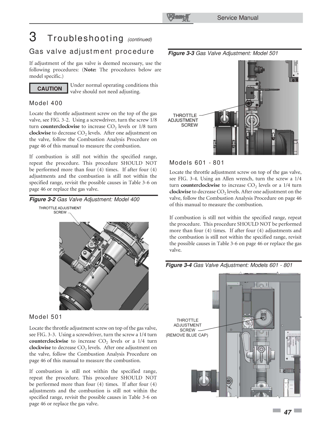
Locate the throttle adjustment screw on the top of the gas valve, see FIG. 3-2. Using a screwdriver, turn the screw 1/8 turn counterclockwise to increase CO2 levels or 1/8 turn clockwise to decrease CO2 levels. After one adjustment on the valve, follow the Combustion Analysis Procedure on page 46 of this manual to measure the combustion.

If combustion is still not within the specified range, repeat the procedure. This procedure SHOULD NOT be performed more than four (4) times. If after four (4) adjustments and the combustion is still not within the specified range, revisit the possible causes in Table 3-6 on page 46 or replace the gas valve.

Figure 3-2Gas Valve Adjustment: Model 400

THROTTLE ADJUSTMENT

SCREW

Model 501

Locate the throttle adjustment screw on top of the gas valve, see FIG. 3-3. Using a screwdriver, turn the screw a 1/4 turn counterclockwise to increase CO2 levels or a 1/4 turn clockwise to decrease CO2 levels. After one adjustment on the valve, follow the Combustion Analysis Procedure on page 46 of this manual to measure the combustion.

If combustion is still not within the specified range, repeat the procedure. This procedure SHOULD NOT be performed more than four (4) times. If after four (4) adjustments and the combustion is still not within the specified range, revisit the possible causes in Table 3-6 on page 46 or replace the gas valve.

Service Manual

Figure 3-3Gas Valve Adjustment: Model 501

Models 601 - 801

Locate the throttle adjustment screw on top of the gas valve, see FIG. 3-4. Using an Allen wrench, turn the screw a 1/4 turn counterclockwise to increase CO2 levels or a 1/4 turn clockwise to decrease CO2 levels. After one adjustment on the valve, follow the Combustion Analysis Procedure on page 46 of this manual to measure the combustion.

If combustion is still not within the specified range, repeat the procedure. This procedure SHOULD NOT be performed more than four (4) times. If after four (4) adjustments and the combustion is still not within the specified range, revisit the possible causes in Table 3-6 on page 46 or replace the gas valve.

Figure 3-4Gas Valve Adjustment: Models 601 - 801

THROTTLE

ADJUSTMENT

SCREW

(REMOVE BLUE CAP)

47

Page 47
Image 47
Lochinvar 400, 801 service manual Gas valve adjustment procedure, Models 601

400, 801 specifications

The Lochinvar 801,400 is a cutting-edge solution in the realm of high-efficiency commercial water heating. This model represents a significant advancement in the design and functionality of water heaters, catering primarily to the demands of large-scale facilities like hotels, hospitals, and large industrial operations.

One of the standout features of the Lochinvar 801,400 is its impressive heating capacity, which can produce up to 801,400 BTUs, making it suitable for high-demand applications. This output is crucial for establishments that require a consistent supply of hot water, such as commercial kitchens and laundry facilities. The robust design ensures that it can handle peak demand periods without compromising performance.

Another significant aspect is the innovative use of advanced technology in its operation. The Lochinvar 801,400 integrates smart controls that enhance its efficiency and ease of operation. These controls allow for precise monitoring and adjustment of water temperatures, ensuring that the system operates within optimal parameters while maximizing energy savings. The intelligent monitoring system can provide real-time updates, making it easier for facility managers to keep track of performance and address maintenance needs proactively.

The construction of the Lochinvar 801,400 incorporates durable materials that not only enhance the longevity of the unit but also offer resistance to corrosion and wear. This durability translates into lower maintenance costs and an extended lifespan for the unit, making it a worthwhile investment for businesses.

Moreover, the Lochinvar 801,400 is designed with energy efficiency in mind. It boasts a high thermal efficiency rating, which reduces operational costs and minimizes the carbon footprint of heating operations. This efficiency is critical in today’s environmentally conscious market, where businesses are seeking to reduce their energy consumption and comply with strict regulations.

The design of the Lochinvar 801,400 also prioritizes safety, featuring innovative safety controls and fail-safes that protect both the unit and the users.

In summary, the Lochinvar 801,400 offers a combination of high capacity, advanced technology, durability, and energy efficiency, making it an excellent choice for commercial water heating solutions. As industries continue to evolve, the demand for reliable and efficient water heating solutions like the Lochinvar 801,400 will only increase.