Full Connectivity Diagram - Appendix #3
Full Connectivity Diagram - Appendix #3
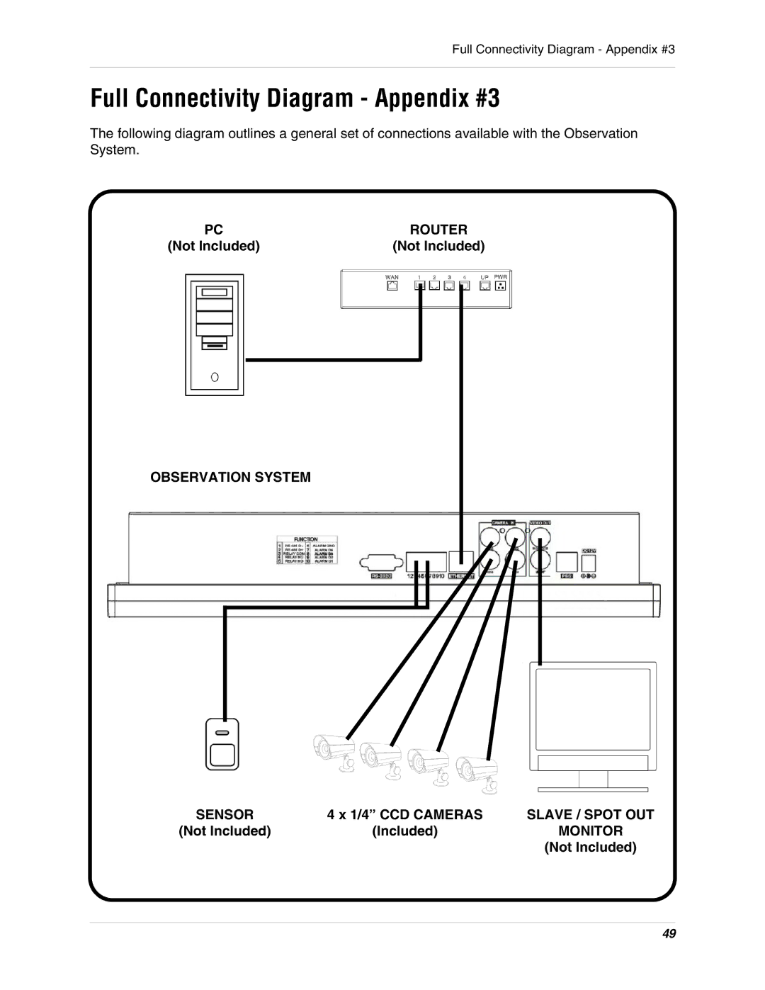
The following diagram outlines a general set of connections available with the Observation System.
PC | ROUTER | ||
(Not Included) | (Not Included) | ||
|
|
|
|
|
|
|
|
OBSERVATION SYSTEM
SENSOR | 4 x 1/4” CCD CAMERAS | SLAVE / SPOT OUT |
(Not Included) | (Included) | MONITOR |
|
| (Not Included) |
49