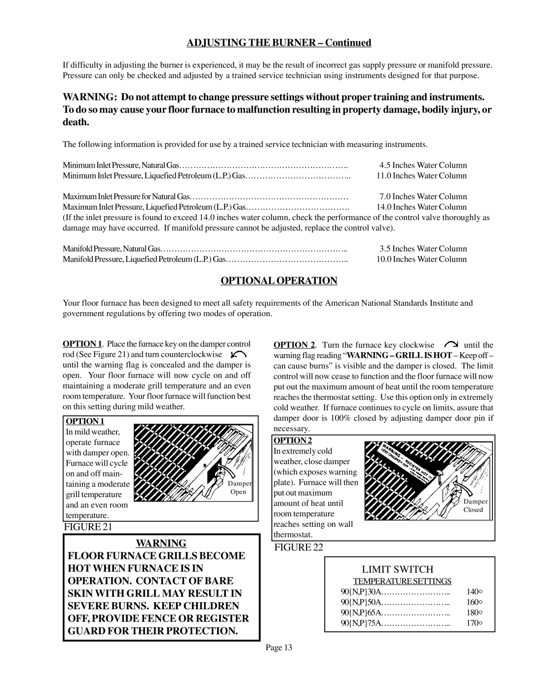
90N50A, 90N30A, 90N65A, 90N75A specifications
Louisville Tin and Stove has established a reputation for quality and innovation in the heating and cooling industry with its line of products, particularly the 90N65A, 90N50A, 90N75A, and 90N30A models. Each of these units boasts distinctive features, technologies, and characteristics that cater to a variety of residential and commercial needs.The 90N65A model stands out for its impressive energy efficiency, designed to operate at an efficiency rating of up to 95%. This model employs advanced condensing technology, which allows it to extract more heat from the combustion process, significantly reducing energy costs for users. Moreover, its variable speed blower promotes quiet operation while optimizing airflow, ensuring that spaces are comfortably heated or cooled without excessive noise.
In contrast, the 90N50A model is engineered for versatility and compactness. This makes it an ideal choice for smaller homes or tight spaces where every inch counts. Despite its size, the 90N50A does not compromise on performance, delivering robust heating capabilities with an efficiency rating also reaching up to 94%. Its straightforward installation process, along with its user-friendly interface, allows for quick setup and ease of operation, appealing to both homeowners and technicians.
The 90N75A model is tailored for larger environments, with a higher BTU output designed to keep extensive areas warm even during the coldest months. It features dual heat exchangers that enhance durability and thermal efficiency, ensuring a longer lifespan. Furthermore, the integrated smart technology allows homeowners to monitor and adjust settings remotely, providing ultimate convenience and control over indoor climates.
Finally, the 90N30A serves as a budget-friendly option without sacrificing quality or efficiency. It incorporates a simplified design that ensures reliability while still achieving a commendable efficiency rating. Ideal for those seeking an economical heating solution, the 90N30A supports both natural gas and propane fuel options, making it adaptable to various energy sources.
All models highlight Louisville Tin and Stove's commitment to sustainability and reducing environmental impact. By incorporating innovative technologies such as modulating burners and advanced heat exchangers, these units not only comply with modern regulatory standards but also contribute to a greener planet. In summary, the Louisville Tin and Stove series—90N65A, 90N50A, 90N75A, and 90N30A—offers a robust selection of heating solutions that cater to diverse needs, emphasizing efficiency, performance, and adaptability.

