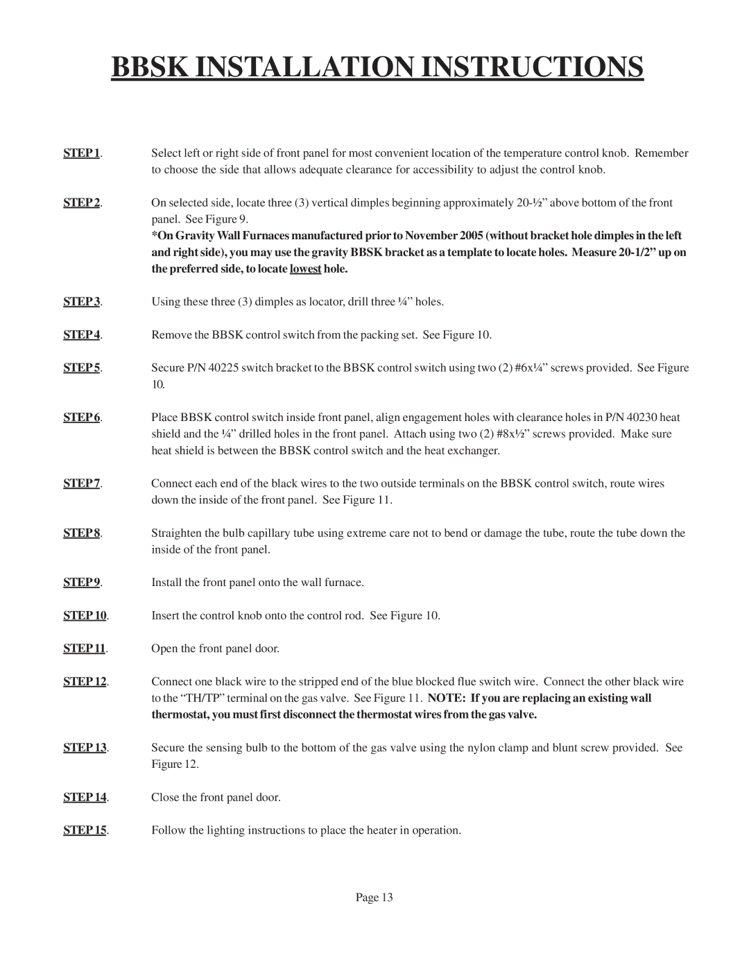
W506F, W505F, W255F, W256F specifications
Louisville Tin and Stove, a well-respected name in the hearth products industry, has made significant strides in delivering high-quality wood and gas stoves. Among their impressive lineup, the models W256F, W505F, W506F, and W255F stand out for their exceptional features, advanced technologies, and distinctive characteristics.The W256F model is renowned for its traditional design paired with modern efficiency. This stove is equipped with a large firebox that allows for longer burn times, ensuring a consistent heat output that effectively warms your living space. Its easy-to-use air control system provides users with optimal combustion, allowing you to adjust the flame intensity for a customized heating experience. The W256F also comes with a sleek glass door, enabling a beautiful view of the fire while maximizing heat retention.
Next in line, the W505F model showcases a more contemporary aesthetic. This stove features an innovative linings technology that promotes even heating and increases fuel efficiency. Its built-in catalytic combustor ensures that most of the smoke and particulate matter generated during combustion is burned off, making it an environmentally friendly choice. The W505F offers customizable trim options, allowing homeowners to match the stove seamlessly with their interior decor.
The W506F is another gem in this collection, notable for its impressive heating capacity. Designed for larger spaces, this model combines power with versatility. It features an advanced convection system that circulates warm air more effectively throughout the room. Additionally, the W506F incorporates a high-efficiency wood-burning design that offers reduced emissions and greater fuel economy, making it a sustainable option for eco-conscious consumers.
Finally, the W255F model caters to those who appreciate a compact yet powerful stove. Ideal for smaller homes or cabins, the W255F delivers robust heat output in a space-saving design. Its quick-response heating capabilities are enhanced by a reliable draft control system that ensures efficient fuel use. This stove also prioritizes safety, equipped with a heat shield to protect surrounding surfaces.
In summary, the Louisville Tin and Stove W256F, W505F, W506F, and W255F models lead the market with their distinctive features and innovative technologies. Together, they offer a range of options for consumers seeking efficiency, aesthetic appeal, and reliable performance. Whether you prefer a traditional classic, contemporary design, or a compact solution, these stoves are engineered to deliver warmth and comfort while upholding environmental standards.
