Section 3: RIM 100sp Installation
You can install the RIM 100 module in some other order if you prefer, but we recommend this installation sequence:
1.Select a flat surface near the display unit to mount the module. The location must be close enough for the RIM's RS232 data cable to reach the display unit's
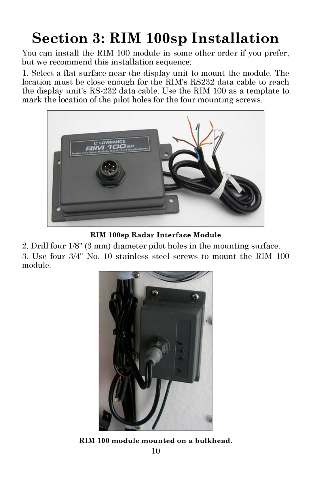
RIM 100sp Radar Interface Module
2.Drill four 1/8" (3 mm) diameter pilot holes in the mounting surface.
3.Use four 3/4" No. 10 stainless steel screws to mount the RIM 100 module.
RIM 100 module mounted on a bulkhead.
10