. . . . . . . . . . . . . . . . . . . . . . . . . . . . . . . . . . . . . . . . . . . . . . . . . . . . . . . . . . . . Power Requirements
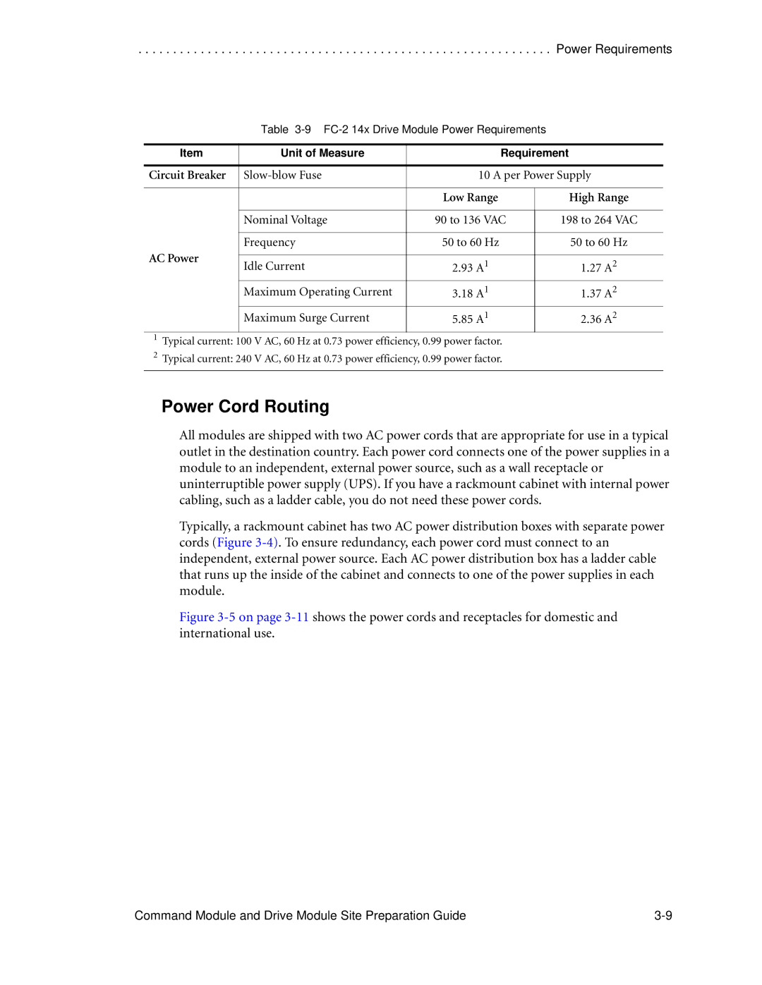
Table 3-9 FC-2 14x Drive Module Power Requirements
Item | Unit of Measure | Requirement | ||
|
|
| ||
Circuit Breaker | 10 A per Power Supply | |||
|
|
|
| |
|
| Low Range | High Range | |
|
|
|
| |
| Nominal Voltage | 90 to 136 VAC | 198 to 264 VAC | |
|
|
|
| |
| Frequency | 50 to 60 Hz | 50 to 60 Hz | |
AC Power |
|
|
| |
Idle Current | 2.93 A1 | 1.27 A2 | ||
| ||||
| Maximum Operating Current | 3.18 A1 | 1.37 A2 | |
| Maximum Surge Current | 5.85 A1 | 2.36 A2 | |
1Typical current: 100 V AC, 60 Hz at 0.73 power efficiency, 0.99 power factor.
2Typical current: 240 V AC, 60 Hz at 0.73 power efficiency, 0.99 power factor.
Power Cord Routing
All modules are shipped with two AC power cords that are appropriate for use in a typical outlet in the destination country. Each power cord connects one of the power supplies in a module to an independent, external power source, such as a wall receptacle or uninterruptible power supply (UPS). If you have a rackmount cabinet with internal power cabling, such as a ladder cable, you do not need these power cords.
Typically, a rackmount cabinet has two AC power distribution boxes with separate power cords (Figure
Figure 3-5 on page 3-11 shows the power cords and receptacles for domestic and international use.
Command Module and Drive Module Site Preparation Guide |