Ladder Cords
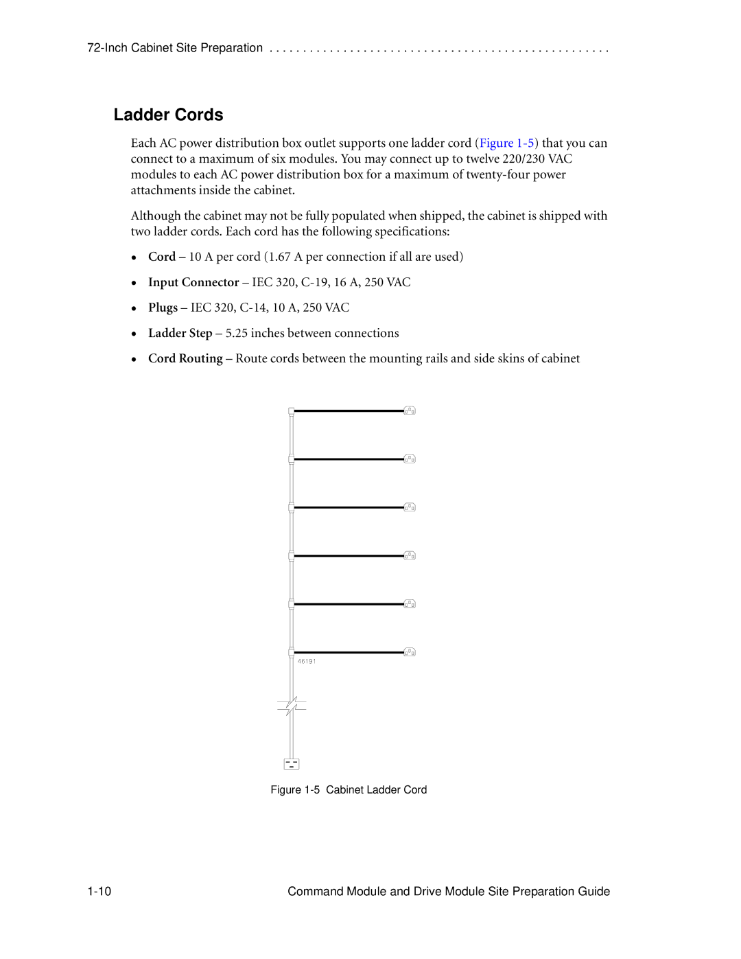
Each AC power distribution box outlet supports one ladder cord (Figure
Although the cabinet may not be fully populated when shipped, the cabinet is shipped with two ladder cords. Each cord has the following specifications:
•
•
•
•
•
Cord – 10 A per cord (1.67 A per connection if all are used)
Input Connector – IEC 320,
Plugs – IEC 320,
Ladder Step – 5.25 inches between connections
Cord Routing – Route cords between the mounting rails and side skins of cabinet
Figure 1-5 Cabinet Ladder Cord
Command Module and Drive Module Site Preparation Guide |