Outside combustion air ducting may be run upwards or vertically through framing and ceil- ing joists, with the hood installed through an outside wall and 3' (914 mm) below the termi- nation. Ducting may also be run downward through floor joists and under the home to a ventilated crawlspace not considered part of the living area of the home.
Note: Do not terminate combustion air kit in attic space under any circumstances.
FTF10-TMS Termination Shroud
An optional termination shroud is available to partially conceal the FTF10-CTDTM when in- stalled on a chase. Model FTF10-TMS is adjust- able for chases measuring a minimum of 27" x 27" (686 mm x 686 mm) up to a maximum of 40 ¹⁄₂" x 40 ¹⁄₂" (1029 mm x 1029 mm). Consult the FTF10-TMS installation instruction for spe- cific installation information.
Glass Doors
If glass doors are to be installed on these fireplaces, refer to specific installation instruc- tions packed with the glass doors. Use only the doors that are listed for use with these fire- places. Use of other non-listed glass door on these fireplaces may constitute a potential fire hazard and is not recommended.
CAUTION: CERTAIN GLASS DOORS OVER- LAP THE BLACK METAL FACING OF THE FIRE- PLACE. IF THE FIREPLACE HAS BEEN FACED WITH NONCOMBUSTIBLE MATERIALS, THERE MIGHT NOT BE SUFFICIENT CLEAR- ANCE TO INSTALL THE GLASS DOORS OF YOUR CHOICE. ENSURE ADEQUATE CLEAR- ANCE IS MAINTAINED AT ALL TIMES SO AS NOT TO INTERFERE WITH THE INSTALLA- TION AND OPERATION OF GLASS DOORS.
GAS LINE CONNECTION
These Elite Series fireplaces have been ap- proved to accept a ¹⁄₂" (13 mm) gas line for an approved gas appliance. Always have the appli- ance installed by a qualified, licensed plumber in accordance with all local building codes. The gas line may enter either side of the fireplace.
CAUTION: PLUMBING CONNECTIONS SHOULD ONLY BE PERFORMED BY A QUALIFIED, LI- CENSED PLUMBER. MAIN GAS SUPPLY MUST BE OFF WHEN PLUMBING GAS LINE TO FIRE- PLACE OR PERFORMING SERVICE.
If you’re installing a gas line, connect it before the fireplace is framed and enclosed in the finished wall. The gas knockout is determined by a 1 ¹⁄₈" (29 mm) round indentation located at the bottom and slightly off center in the side refractories.
THE KNOCKOUT IS ALWAYS REMOVED FROM INSIDE THE FIREPLACE. DO NOT REMOVE THE KNOCKOUT UNLESS YOU ARE INSTALL- ING A GAS LINE. If removal is attempted from the outer wrapper, side-refractory damage may occur. With a medium-sized hammer, lightly tap the surface of the indentation. The refrac- tory material is very thin in this area and is easily removed. Once a small hole has been made, continue tapping until you have reached suffi- cient diameter for the gas line to fit through. The entire knockout does not have to be removed. Remove insulation in the gas line channel.
Install a ¹⁄₂" (13 mm) gas supply line through fireplace wall for connection to a decorative gas appliance inside the firebox. Outside, the gas supply line connects to a gas shut-off valve recessed flush into the wall or floor. The valve should be controlled by a removable valve key for safety.
Always plumb gas line installation per local codes. Check all connections and test for gas leaks, using a gas leak test solution (also referred to as bubble leak solution).
Note: Using a soapy water solution (50% dish soap, 50% water) is an effective leak test solution but it is not recommended, because the soap residue that is left on the pipes/ fittings can result in corrosion over time. Never
use an open flame to check for leaks.
IMPORTANT: RE-PACK INSULATION MATE- RIAL IN SQUARE HOLE AROUND GAS LINE; INTERIOR AND EXTERIOR, TO SEAL.
This provision is intended only for connection to a decorative gas appliance incorporating an automatic shut-off device and complying with the standard for Decorative Gas Appliances for installation in vented fireplaces, ANSI Z21.60. Install in accordance with the National Fuel Gas Code, ANSI Z223.1. This complies with the revised U.L. 127 standard.
CAUTION: WHEN USING THE DECORATIVE GAS APPLIANCE, THE FIREPLACE DAMPER MUST BE SET IN THE FULLY OPEN POSITION.
Vent Free Appliances
These units have been tested and approved to ANSI/IAS/AGA Z21.11.2 for use with unvented gas appliances and complies with the stan- dard for Factory-Built fireplaces, UL 127.
The unit has been tested for use with any unvented gas log sets having a maximum rating of 40,000 BTU. The minimum mantle configu- rations are outlined in Figures 45 and 46.
NOTE: DIAGRAMS & ILLUSTRATIONS NOT TO SCALE.
These fireplaces have been marked with a maximum rating of 40,000 BTU to assure that homeowners do not exceed the allowable lim- its for all allowed installations of mantles.
NEVER INSTALL AN UNVENTED GAS LOG SET WITH A BTU GREATER THAN 40,000.
COLD CLIMATE INSULATION
If you live in a cold climate, it is especially important to seal all cracks around the fireplace opening with noncombustible material and wher- ever cold air could enter the room. Surrounding materials must be caulked where it meets the black metal facing of the fireplace to avoid cold air intrusion. Use noncombustible caulking ma- terial only on fireplace facing to seal. Also, the outside air inlet duct should be wrapped with noncombustible insulation to minimize the for- mation of condensation. Do not place insulation materials against chimney sections.
Note: A 2" (51 mm) air space must be preserved for all combustible materials extending for any continuous length adjacent to the chimney.
It is especially important to insulate between the studs of an outside chase cavity and under the floor if the floor is above ground level. Do not place insulation directly against the fire- place or chimney system
FIREPLACE FINISHES
Mantels and Trim
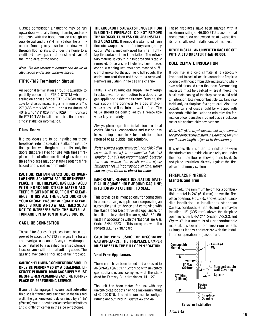
In Canada, the minimum height for a combus- tible mantel is 24" (610 mm) above the fire- place opening. Figure 45 shows typical Cana- dian installation. In installations other than Canada, combustible mantels and trim may be installed 12" (305 mm) above the fireplace opening as per NFPA 211; Section 7-2.3.3. and Figure 46. If a mantel is of a noncombustible material, it is exempt from these requirements as long as it does not interfere with the instal- lation or operation of glass doors.
Combustible | Finished |
Mantel | Wall |
8" Max.
(203mm)Noncombustible
Wall Covering
Facing
Flush
Fireplace
Opening
Canadian Installation
Figure 45
15