Black Portion Of Frame


Not To Be Covered With


Combustible Materials


Wall

4 ³⁄₄”

Covering

15°


¹⁄₂”

Door

Opening


Safe

18”

Zone

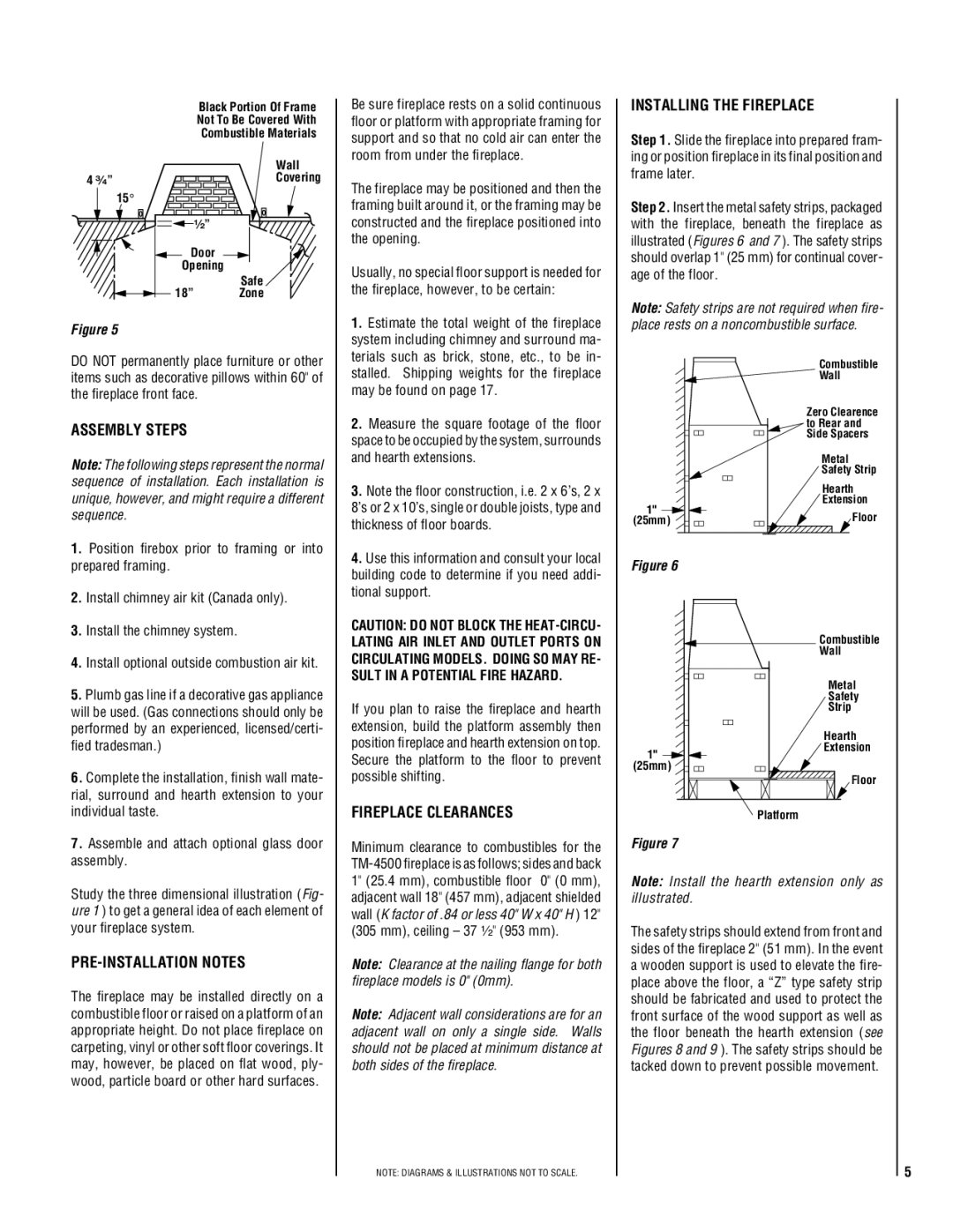
Figure 5

DO NOT permanently place furniture or other items such as decorative pillows within 60" of the fireplace front face.

ASSEMBLY STEPS

Note: The following steps represent the normal sequence of installation. Each installation is unique, however, and might require a different sequence.

1.

Position firebox prior to framing or into

prepared framing.

2.

Install chimney air kit (Canada only).

3.

Install the chimney system.

4.

Install optional outside combustion air kit.

Be sure fireplace rests on a solid continuous floor or platform with appropriate framing for support and so that no cold air can enter the room from under the fireplace.

The fireplace may be positioned and then the framing built around it, or the framing may be constructed and the fireplace positioned into the opening.

Usually, no special floor support is needed for the fireplace, however, to be certain:

1.Estimate the total weight of the fireplace system including chimney and surround ma- terials such as brick, stone, etc., to be in- stalled. Shipping weights for the fireplace may be found on page 17.

2.Measure the square footage of the floor space to be occupied by the system, surrounds and hearth extensions.

3.Note the floor construction, i.e. 2 x 6’s, 2 x 8’s or 2 x 10’s, single or double joists, type and thickness of floor boards.

4.Use this information and consult your local building code to determine if you need addi- tional support.

CAUTION: DO NOT BLOCK THE HEAT-CIRCU- LATING AIR INLET AND OUTLET PORTS ON CIRCULATING MODELS. DOING SO MAY RE- SULT IN A POTENTIAL FIRE HAZARD.

INSTALLING THE FIREPLACE

Step 1. Slide the fireplace into prepared fram- ing or position fireplace in its final position and frame later.

Step 2. Insert the metal safety strips, packaged with the fireplace, beneath the fireplace as illustrated (Figures 6 and 7 ). The safety strips should overlap 1" (25 mm) for continual cover- age of the floor.

Note: Safety strips are not required when fire- place rests on a noncombustible surface.

Combustible

Wall

Zero Clearence to Rear and Side Spacers

Metal

Safety Strip

Hearth

Extension

1"

Floor

(25mm)

Figure 6

Combustible

Wall

5. Plumb gas line if a decorative gas appliance

will be used. (Gas connections should only be

performed by an experienced, licensed/certi-

fied tradesman.)

6. Complete the installation, finish wall mate-

rial, surround and hearth extension to your

If you plan to raise the fireplace and hearth extension, build the platform assembly then position fireplace and hearth extension on top. Secure the platform to the floor to prevent possible shifting.

1" (25mm)

Metal

Safety

Strip

Hearth Extension

Floor

individual taste.

7. Assemble and attach optional glass door

assembly.

Study the three dimensional illustration (Fig- ure 1 ) to get a general idea of each element of your fireplace system.

PRE-INSTALLATION NOTES

The fireplace may be installed directly on a combustible floor or raised on a platform of an appropriate height. Do not place fireplace on carpeting, vinyl or other soft floor coverings. It may, however, be placed on flat wood, ply- wood, particle board or other hard surfaces.

FIREPLACE CLEARANCES

Minimum clearance to combustibles for the TM-4500 fireplace is as follows; sides and back 1" (25.4 mm), combustible floor 0" (0 mm), adjacent wall 18" (457 mm), adjacent shielded wall (K factor of .84 or less 40" W x 40" H ) 12" (305 mm), ceiling – 37 ¹⁄₂" (953 mm).

Note: Clearance at the nailing flange for both fireplace models is 0" (0mm).

Note: Adjacent wall considerations are for an adjacent wall on only a single side. Walls should not be placed at minimum distance at both sides of the fireplace.

NOTE: DIAGRAMS & ILLUSTRATIONS NOT TO SCALE.

Platform

Figure 7

Note: Install the hearth extension only as illustrated.

The safety strips should extend from front and sides of the fireplace 2" (51 mm). In the event a wooden support is used to elevate the fire- place above the floor, a “Z” type safety strip should be fabricated and used to protect the front surface of the wood support as well as the floor beneath the hearth extension (see Figures 8 and 9 ). The safety strips should be tacked down to prevent possible movement.

5

Page 5
Image 5
Lucent Technologies TM-4500 Assembly Steps, Installing the Fireplace, PRE-INSTALLATION Notes, Fireplace Clearances

TM-4500 specifications

Lucent Technologies TM-4500 is a highly regarded platform in the world of telecommunications, known for its robust functionality and adaptability in various network environments. As an integral component of Lucent's product lineup, the TM-4500 serves a diverse range of applications, enhancing the capabilities of service providers and businesses alike.

One of the main features of the TM-4500 is its versatile architecture, which supports a variety of communication protocols, including TDM, ATM, and IP. This interoperability allows for seamless integration into existing networks, providing carriers and enterprises the flexibility to upgrade and evolve their systems without incurring excessive costs. This adaptability ensures that clients can customize their solutions to meet specific operational requirements.

Another key characteristic of the TM-4500 is its emphasis on reliability and performance. The platform is designed for high availability, ensuring continuous operation even under demanding conditions. This is crucial for telecommunications networks where downtime can result in significant financial losses and customer dissatisfaction. The TM-4500 incorporates advanced redundancy features that help maintain service integrity, contributing to its reputation as a dependable solution in critical environments.

The TM-4500 also stands out with its powerful processing capabilities and scalability. As networks grow and data traffic increases, the platform can be expanded to accommodate higher bandwidth needs. Its modular design allows operators to add or upgrade components without extensive overhauls, thereby enhancing the lifespan of the investment. This capability is essential for businesses looking to future-proof their communications infrastructure.

In terms of network management, the TM-4500 is equipped with sophisticated monitoring and diagnostic tools. These features enable real-time performance tracking and troubleshooting, assisting operators in maintaining optimal service levels. The platform’s user-friendly interface helps streamline network management tasks, reducing the complexity often associated with large-scale telecommunications operations.

Security is another important aspect of the TM-4500. As cyber threats continue to evolve, the platform includes robust security protocols to safeguard data and ensure secure communications. This is increasingly vital in a landscape where data breaches can have severe repercussions.

In summary, the Lucent Technologies TM-4500 stands out in the telecommunications sphere due to its versatile architecture, reliability, scalability, advanced network management tools, and strong security features. This combination makes it a preferred choice for service providers and enterprises looking to enhance their communications infrastructure.