REMOVING THE OLD THERMOSTAT

Switch electricity to the furnace and air conditioner OFF; then proceed with the following steps.

1.Remove cover from old thermostat. Most are snap-on types and simply pull off. Some have locking screws on the side. These must be loosened.

2.Note the letters printed near the terminals. Attach labels (enclosed) to each wire for identification. Remove and label wires one at a time. Make sure the wires do not fall back inside the wall.

3.Loosen all screws on the old thermostat and remove it from the wall.

C A U T I O N

Read instructions carefully before removing any wiring from existing thermostat.

Wires must be labeled before

they are removed. When removing wires from their terminals, ignore the color of the wires since these may not comply with the standard.

WIRING DIAGRAMS

HEATING ONLY SYSTEMS

COOLING ONLY SYSTEMS


RC-RH JUMPER


RC-RH JUMPER


PROVIDED


PROVIDED

Y O G W B RH RC

Y O G W B RH RC

WIRE

G

W

RH

Y

G

RH

F

H

RC

C*

F

RC

FAN


4

R

6


R

OPTIONAL


V


V


5


5


MOUNTING THE UNIT ON THE WALL

1.Strip insulation 3/8 in. (9.5mm) from wire ends and clean off any corrosion.

2.Fill wall opening with non-combustible insulation to prevent drafts from affecting the thermostat.

3. Press up on the button on bottom of thermostat and swing the body away from the base and up to remove the body from the base.

C A U T I O N

Be careful not to drop the body or disturb electronic parts.

Leave the cover closed while the body is being removed from the base.

W3G Y W RH B O RC L

TERMINALS

G


O

R


SCREWBASE

ANCHORS

N O T E

If you are mounting the base to a soft material like plasterboard or if you are using the old mounting holes, the screws may not hold. Drill a 3/16-in. (4.8mm) hole at each screw location, and insert the plastic anchors provided. Then mount the base as described below.

Attaching Wires

4.Hold the base against the wall, with the wires coming through wherever it is convenient for wiring. Route the wires to below the terminal block. Position the base for best appearance (to hide any marks from an old thermostat). An optional wall plate is included for covering old mounting holes. Attach the base to the wall with the two screws provided.

C A U T I O N Do not allow wires to touch each other or parts on thermostat. Wires must be trapped between black spacer and brass terminal. Also, be sure to tighten securely all 7 electrical terminal screws.

HEATING / COOLING SYSTEMS

HEATING / COOLING SYSTEMS

4 -WIRES WITH ONE TRANSFORMER


5 -WIRES WITH TWO TRANSFORMERS


RC-RH JUMPER


RC-RH JUMPER


PROVIDED


REMOVED

Y O G W B RH RC

Y O G W B RH RC

Y

G

W

RH

Y

G

W

RH

RC

C*

F

H

RC

C*

F

H

V

R

6


4

R

6


4

5


V


5


TYPICAL SINGLE STAGE

WIRING DIAGRAM NOTES


HEAT PUMP WIRING


(APPLIES TO ALL DRAWINGS)

*CUSTOMER


SUPPLIED


RC-RH JUMPER

• The DASHED lines are optional

JUMPER


PROVIDED

Y O

G

W B

RH RC

depending upon your system type.


• Verify whether “C”, “X” or “B” wires


are connected to system common.


• If “B” and “O” are both present, it is

Y

O G

B

RH

likely that “B” is a system common.

• If a “B” wire in your system is a

C*

F


RC


R

common, then connecting it to the


“B” terminal may cause damage to


V


your system.


5


• If “Y” and “C” are both present, it is


USE B or O NOT BOTH


likely that “C” is a system common.

These diagrams below are provided for new installations or

unreferenced wires.

TYPICAL HOOKUP FOR 2 OR 3 WIRE

24 VAC HEATING SYSTEMS (AND MILLIVOLT)

Y O G W B RH RC


COMMON


OPTIONAL


RH-RC JUMPER


FAN LEAD


PROVIDED

Gas

FAN Valve System

or XFMR

Heater

TYPICAL COOL HOOKUP

24 VAC SYSTEMS

Y O G W B RH RC


RH-RC JUMPER


SYSTEM


PROVIDED


COMMON


A/C


FAN


System

Comp.


XFMR


2

Page 2
Image 2
Lux Products TX9000 installation instructions Mounting the Unit on the Wall, Removing the OLD Thermostat

TX9000 specifications

The Lux Products TX9000 is a highly advanced programmable thermostat designed to enhance both comfort and energy efficiency in homes. With its user-friendly interface and a suite of smart features, it has become a popular choice among homeowners looking to optimize their heating and cooling systems.

One of the standout features of the TX9000 is its intuitive touchscreen display. The full-color display makes it easy to navigate through various settings and options. Users can easily adjust the temperature, set schedules, and access different modes with just a few taps. The interface is designed to be simple and straightforward, so even those who are not tech-savvy can operate it with ease.

The TX9000 offers advanced scheduling capabilities, allowing homeowners to create personalized heating and cooling schedules. It can be programmed for up to seven days, with multiple settings per day, meaning you can customize it based on your lifestyle and preferences. This not only maximizes comfort but also contributes to energy savings, as the system can be set to lower temperatures when the home is unoccupied.

Another key feature of the TX9000 is its energy-saving technology. The thermostat monitors energy consumption and provides reports that help users make informed decisions about their energy use. This feature enables homeowners to lower their energy bills by running the HVAC system more efficiently.

Additionally, the TX9000 is equipped with Smart Wi-Fi capabilities, allowing users to control their home climate from anywhere using a smartphone app. This connectivity means you can adjust settings while at work, on vacation, or simply lounging on the couch, ensuring the home is always at your desired temperature when you arrive.

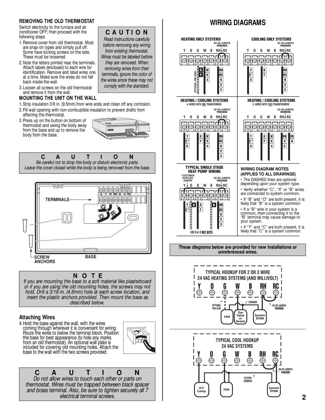
Furthermore, the thermostat supports a variety of heating and cooling systems, making it a flexible option for many households. Its compatibility with various models ensures that it can seamlessly integrate into most existing HVAC setups without requiring significant modifications.

Overall, the Lux Products TX9000 stands out for its user-friendly design, customizable scheduling, energy-saving features, and smart app connectivity. It's an excellent choice for anyone looking to manage their home's climate efficiently while keeping energy consumption and costs in check. With its impressive array of features, the TX9000 is paving the way for smarter home temperature management.