55P916 60P916 64P916
Warranty Verification
Safety Instructions Read before operating equipment
Table of Contents
Standard TV broadcast VHF/UHF or Cable TV
Features
SHARPNESS, TINT, Picture
Picture Menu Control Adjustments
COLOR, Brightness
Select Clearview control
Picture Menu Controls
Press the outer Menu ring
Press the Status button to
Select Convergence
RED/BLUE Convergence
Select Flesh
Flesh Correction
Correction control
Press the Menu ring
Picture Source
Feature Menu Control Adjustments
Select Picture Source Select control
Press the Menu ring buttons to move the RED
Closed Caption
Feature Menu Controls
Select Closed Captioning control
Text 1, 2, 3
Cable Tuning
Select Channel Memory
Channel Memory AUTO-PROGRAMMING
Press the center Menu button to
Press the Status or Menu
Select Channel Memory ADD/DELETE Channels control
ADD/DELETE Channels
Press the remotes number
SET Clock
Select SET Clock control
Select SET Alarm Timer
SET Alarm Timer
Center Menu buttons to
Press the remotes number
Press the Sleep button on
Sleep Timer
Press the Sleep button
Press the Status or Menu
Select Channel Display control
Channel Display
Half Hour Reminder
Select Half Hour Reminder control
Parental Control
Setup Code Number
Select the Block Channels control
Parental Control Channel Blocking
Enter the correct Parental
Content Advisory
Select the Content
Press the Menu ring Center Menu buttons to
Content Advisory Movie Ratings
Select the Movie Ratings Menu option
Press the Menu ring Left
Parental Guidelines
Right side buttons to
Center Menu buttons to Block
Review Settings
Content Advisory Blocking Options
Select the Blocking Options Menu control
Select the Review
Channel Labels
With the Feature Menu
Display control
Language
Select the Language
Left and Right buttons to adjust
Sound Menu Control Adjustments
BASS, TREBLE, Balance
Select BASS, or TREBLE, or
Stereo
Sound Menu Controls
Select Stereo sound control
Second Audio Program
Select the Incredible
Incredible STERE0
Select Display Volume
Display Volume
Connect the Right and Left
TV Speakers
Variable Audio OUT jacks
TV Speakers control
Connect both external
Surround Sound
Place the speakers so
Variable Audio Output
AUX 1 Video Inputs
Using the AUDIO/VIDEO Input Jacks
Connect the Video OUT jack from the VCR to the AUX
Connect the Audio OUT jacks Right and Left from
Connect the Video OUT jack
Side Video Inputs
Connect the Audio OUT
Select the Side Video
AUX1 S-VIDEO Inputs
Component Video Inputs provide for the highest
Component Video Inputs
Connect the Component Y PB
Select the AUX 1 Y PB PR Picture Source control on the TV
AUDIO/VIDEO Outputs
Auto Picture
Remote Control Operation
Press the Auto button on
Press the outer Menu ring top
Press the Auto button on the remote
Auto Picture
Change Label
Finished
Press the Auto button on the remote With the Auto Menu on
Auto Sound
Are you tired of the sound of commercials following you
Surf list
Setting the TV Remote to Work Accessory Devices
Please read through all the steps before beginning
Direct Access Method
Your TV remote can be set to work various accessory
Setting the Remote to Work Other Devices Search
Search Method
Device. Point the remote toward
VCR Brand Remote Code no
Remote Control Direct Entry Codes for Accessory Devices
041
030, 035, 038, 040, 028
Allegro 180 Antronix 049 Archer 049, 180, 234
294
TV-VCR AV Button
Using the Remotes VCR Buttons
HOW to USE the PICTURE-IN-PICTURE PIP Feature
Place the TVs PIP Source
Turn the TV on
Select control to ANT B
Also place the TVs Main
Press the PIP ON/OFF button to show the PIP picture
Using PIP with the Remote Control
Press the Swap button to swap
Press Freeze to hold
PIP Source
Selecting the Picture Source for PIP
Select PIP Source control
AUX 1 or 2 Video for a
Left and Right buttons to adjust
Adjusting Picture -IN -PICTURE Color and Tint
PIP Color / PIP Tint
Select PIP Color or PIP
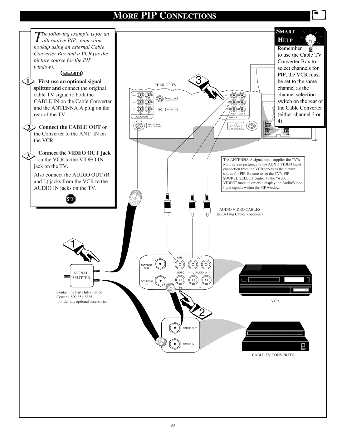
Signal Splitter
First use an optional signal
More PIP Connections
Audio Video Cables
Select Help on the TVs
TV Help Menu
Press the center Menu button to
Press the Menu ring and then
Tips if Something Isnt Working
TV Displays Wrong Channel or No Channels Above
Glossary to Television Terms
Index
Renewed