SETUP
Connections
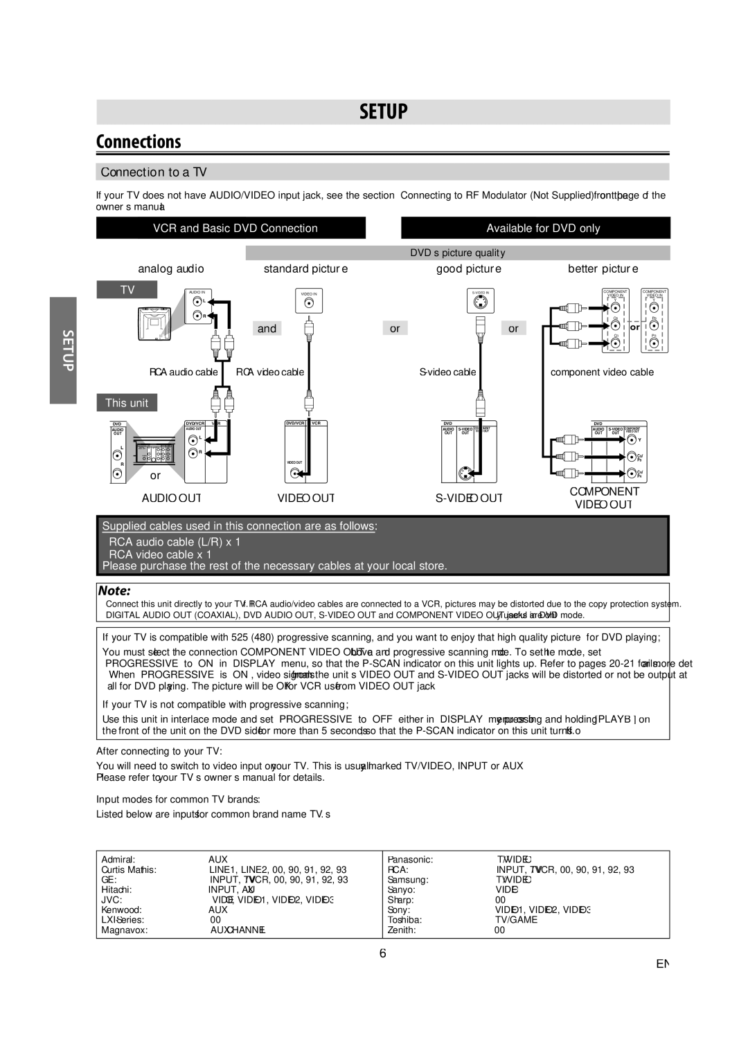
Connection to a TV
If your TV does not have AUDIO/VIDEO input jack, see the section “Connecting to RF Modulator (Not Supplied)” on the front page of the owner’s manual.
VCR and Basic DVD Connection |
| Available for DVD only |
|
|
|
SETUP
analog audio
TV | AUDIO IN |
L
R
RCA audio cable
|
|
|
|
|
|
|
|
|
| DVD’s picture quality |
|
|
| ||
|
| standard picture |
|
|
|
| good picture | ||||||||
|
|
|
| VIDEO IN |
|
|
|
| |||||||
|
|
|
|
|
|
|
|
|
|
|
|
|
|
|
|
|
| and |
|
|
|
| or |
|
|
|
|
|
| or |
|
|
|
|
|
|
|
|
|
|
|
|
|
|
|
|
|
RCA video cable |
|
|
|
|
|
|
|
|
|
| |||||
|
|
|
|
|
|
|
|
|
|
|
|
|
|
|
|
|
|
|
|
|
|
|
|
|
|
|
|
|
|
|
|
better picture
COMPONENT | COMPONENT | |
| VIDEO IN | VIDEO IN |
| Y | Y |
|
|
|
CBPB
or
CRPR
component video cable
This unit
DVD |
| DVD/VCR |
AUDIO | AUDIO OUT | |
OUT |
| |
L
L
R
R![]()
![]() or
or
AUDIO OUT
DVD/VCR | VCR |
VIDEO OUT |
|
VIDEO OUT
| DVD |
|
|
DIGITAL | AUDIO | COMPONENT | |
VIDEO OUT | |||
AUDIO OUT | OUT | OUT |
|
COAXIAL |
|
|
|
DVD
DIGITAL | AUDIO | COMPONENT | |
VIDEO OUT | |||
AUDIO OUT | OUT | OUT |
|
|
|
| Y |
|
|
| CB/ |
COAXIAL |
|
| PB |
|
|
| CR/ |
|
|
| PR |
COMPONENT VIDEO OUT
Supplied cables used in this connection are as follows:
•RCA audio cable (L/R) x 1
•RCA video cable x 1
Please purchase the rest of the necessary cables at your local store.
Note:
•Connect this unit directly to your TV. If RCA audio/video cables are connected to a VCR, pictures may be distorted due to the copy protection system.
•DIGITAL AUDIO OUT (COAXIAL), DVD AUDIO OUT,
If your TV is compatible with 525 (480) progressive scanning, and you want to enjoy that high quality picture for DVD playing;
You must select the connection COMPONENT VIDEO OUT above and progressive scanning mode. To set the mode, set “PROGRESSIVE” to “ON” in “DISPLAY” menu, so that the
•When “PROGRESSIVE” is “ON”, video signals from the unit’s VIDEO OUT and
If your TV is not compatible with progressive scanning;
Use this unit in interlace mode and set “PROGRESSIVE” to “OFF” either in “DISPLAY” menu or by pressing and holding [PLAY B] on the front of the unit on the DVD side for more than 5 seconds, so that the
After connecting to your TV:
You will need to switch to video input on your TV. This is usually marked TV/VIDEO, INPUT or AUX.
Please refer to your TV’s owner’s manual for details.
Input modes for common TV brands:
Listed below are inputs for common brand name TV’s.
Admiral: | AUX | Panasonic: | TV/VIDEO |
Curtis Mathis: | LINE1, LINE2, 00, 90, 91, 92, 93 | RCA: | INPUT, TV/VCR, 00, 90, 91, 92, 93 |
GE: | INPUT, TV/VCR, 00, 90, 91, 92, 93 | Samsung: | TV/VIDEO |
Hitachi: | INPUT, AUX | Sanyo: | VIDEO |
JVC: | VIDEO, VIDEO1, VIDEO2, VIDEO3 | Sharp: | 00 |
Kenwood: | AUX | Sony: | VIDEO1, VIDEO2, VIDEO3 |
00 | Toshiba: | TV/GAME | |
Magnavox: | AUX CHANNEL | Zenith: | 00 |
|
|
|
|
6
EN