Adjusting fastening torque
The fastening torque can be adjusted in sixDrill marking stages by turning the adjusting ring so that
the pointer on the adjusting ring points to
anumber on the tool body. The fastening torque i s minimum when the pointer points
to the number 1 and maximum when it | ‘ | ?\\ | ||
marking. | marking. The | clutch | ||
points to the |
|
| ||
will slip a t varying torque levels when the |
|
| ||
pointer is set a t the numbers 1 to 5. The | Adiusting ring |
| ||
clutch is designed not to slip a t the | - 8 - |
|
| |
Before actual operation, drive a trial screw into your material or a piece of duplicate material to determine which torque level is required for a particular application.
NOTE :
The adjusting ring cannot be locked with the pointer positioned
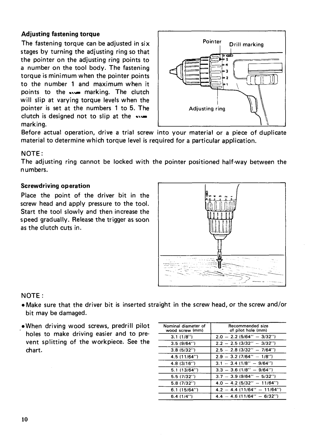
Screwdriving operation
Place the point of the driver bit in the screw head and apply pressure to the tool. Start the tool slowly and then increase the speed gradually. Release the trigger as soon as the clutch cuts in.
NOTE :
0 Make sure that the driver bit is inserted straight in the screw head, or the screw and/or bit may be damaged.
![]() When driving wood screws, predrill pilot holes to make driving easier and to pre- vent splitting of the workpiece. See the chart.
When driving wood screws, predrill pilot holes to make driving easier and to pre- vent splitting of the workpiece. See the chart.
Nominal diameter of | Recommended size |
wood screw Imm) | of pilot hole 1”) |
3.111 /E”)2.0 - 2.2 15/64“ - 3/32’,)
3.519/64’,) 2.2 - 2.513/32” - 3/32“)
3.815/32”) 2.5 - 2.8 13/32” - 7/64’)
4.5111/64“) 2.9 - 3.2 17/64” - 1/8”)
4.813/16”) 3.1 - 3.4(1/8”- 9/64’,)
5.1113/64”) 3.3 - 3.6 11/8”- 9/64’,)
5.517/32”) 3.7 - 3.9 19/64” - 5/32’,)
5.817/32”) 4.0- 4.2 15/32” - 11/64”)
6.1( 1 5/64’,) 4.2 - 4.4I1 1/64” - 11/64’)
6.411/4”) 4.4 - 4.6 11 1/64” - 6/32”)
10