002102
21
3
4
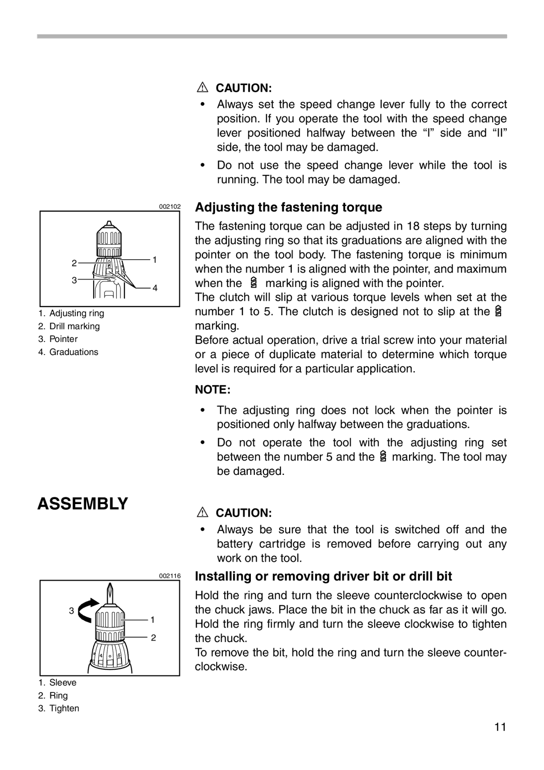
1.Adjusting ring
2.Drill marking
3.Pointer
4.Graduations
CAUTION:
•Always set the speed change lever fully to the correct position. If you operate the tool with the speed change lever positioned halfway between the “I” side and “II” side, the tool may be damaged.
•Do not use the speed change lever while the tool is running. The tool may be damaged.
Adjusting the fastening torque
The fastening torque can be adjusted in 18 steps by turning the adjusting ring so that its graduations are aligned with the pointer on the tool body. The fastening torque is minimum when the number 1 is aligned with the pointer, and maximum
when the ![]() marking is aligned with the pointer.
marking is aligned with the pointer.
The clutch will slip at various torque levels when set at the number 1 to 5. The clutch is designed not to slip at the ![]() marking.
marking.
Before actual operation, drive a trial screw into your material or a piece of duplicate material to determine which torque level is required for a particular application.
NOTE:
•The adjusting ring does not lock when the pointer is positioned only halfway between the graduations.
•Do not operate the tool with the adjusting ring set between the number 5 and the ![]() marking. The tool may be damaged.
marking. The tool may be damaged.
ASSEMBLY
002116
3
1
2
1.Sleeve
2.Ring
3.Tighten
CAUTION:
•Always be sure that the tool is switched off and the battery cartridge is removed before carrying out any work on the tool.
Installing or removing driver bit or drill bit
Hold the ring and turn the sleeve counterclockwise to open the chuck jaws. Place the bit in the chuck as far as it will go. Hold the ring firmly and turn the sleeve clockwise to tighten the chuck.
To remove the bit, hold the ring and turn the sleeve counter- clockwise.
11