P 16/20
 Repair
[3]DISASSEMBLY/ASSEMBLY
[3]-7. Trigger Valve Section
ASSEMBLING
1)Mount O rings to Pilot valve as described in Fig. 30.
2)Assemble Trigger valve section. (Refer to the bottom illustration in Fig. 29.)
When assembling Trigger valve guide to Trigger valve case, push it toward Trigger valve case until it snaps in place.
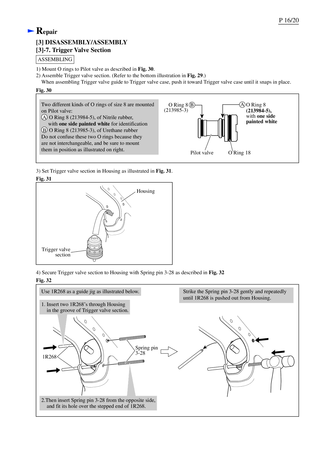
Fig. 30
Two different kinds of O rings of size 8 are mounted on Pilot valve:
A O Ring 8
BO Ring 8
O Ring 8 | B | A O Ring 8 |
|
| |
|
| with one side |
|
| painted white |
Pilot valve | O Ring 18 |
3)Set Trigger valve section in Housing as illustrated in Fig. 31.
Fig. 31
Housing
Trigger valve section
4)Secure Trigger valve section to Housing with Spring pin
Fig. 32
Use 1R268 as a guide jig as illustrated below.
1.Insert two 1R268’s through Housing in the groove of Trigger valve section.
Strike the Spring pin
| Spring pin |
1R268 | |
|
2.Then insert Spring pin