|
|
|
| P 12/17 |
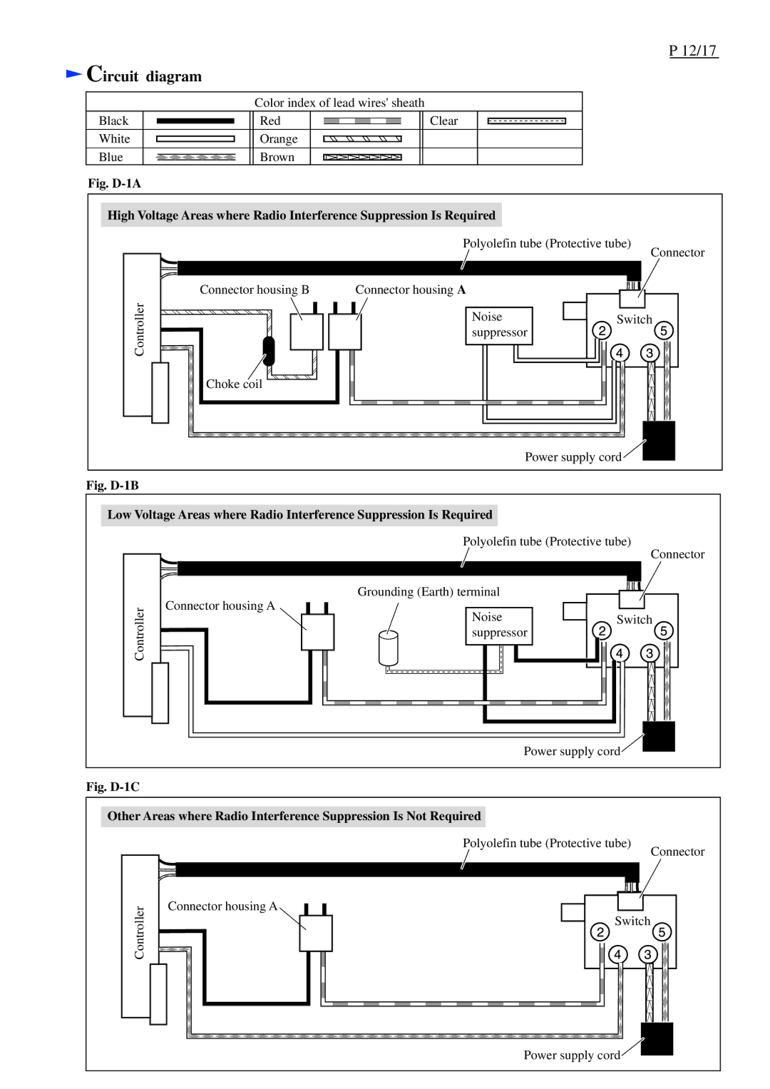
Circuit diagram |
|
|
| |
| Color index of lead wires' sheath |
|
| |
Black | Red | Clear |
|
|
White | Orange |
|
|
|
Blue | Brown |
|
|
|
Fig. |
|
|
|
|
High Voltage Areas where Radio Interference Suppression Is Required |
|
| ||
|
| Polyolefin tube (Protective tube) | Connector | |
|
|
|
| |
| Connector housing B | Connector housing A |
|
|
Controller |
| Noise | Switch | |
| suppressor |
| ||
|
|
|
| |
| Choke coil |
|
|
|
|
|
| Power supply cord |
|
Fig. D-1B
Low Voltage Areas where Radio Interference Suppression Is Required
Polyolefin tube (Protective tube)
Connector
Controller
Connector housing A
Grounding (Earth) terminal |
|
Noise | Switch |
suppressor |
|
Power supply cord |
Fig. |
|
|
Other Areas where Radio Interference Suppression Is Not Required |
| |
| Polyolefin tube (Protective tube) | Connector |
|
| |
Controller | Connector housing A |
|
Switch |
| |
|
| |
| Power supply cord |
|
