P 3/17
 Repair
[3]DISASSEMBLY/ASSEMBLY
[3]-1. Chuck Section
DISASSEMBLY
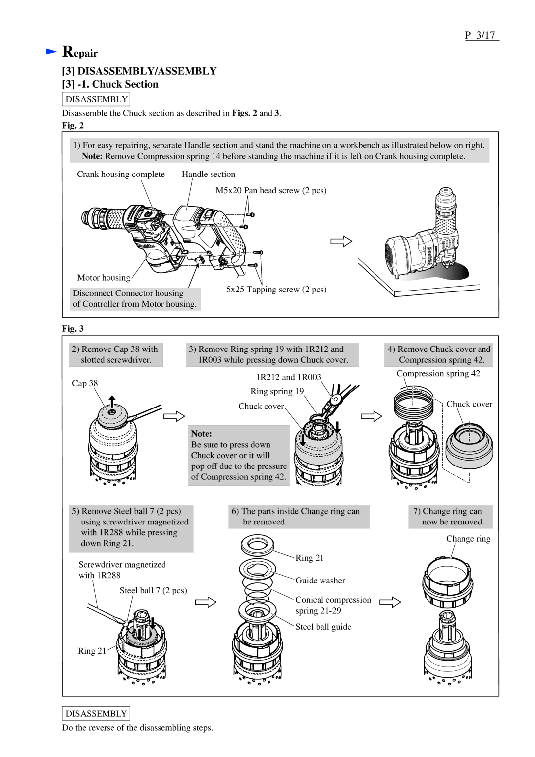
Disassemble the Chuck section as described in Figs. 2 and 3.
Fig. 2
1)For easy repairing, separate Handle section and stand the machine on a workbench as illustrated below on right. Note: Remove Compression spring 14 before standing the machine if it is left on Crank housing complete.
Crank housing complete | Handle section |
M5x20 Pan head screw (2 pcs)
Motor housing |
|
Disconnect Connector housing | 5x25 Tapping screw (2 pcs) |
| |
of Controller from Motor housing. |
|
Fig. 3 |
|
2)Remove Cap 38 with slotted screwdriver.
Cap 38
5)Remove Steel ball 7 (2 pcs) using screwdriver magnetized with 1R288 while pressing down Ring 21.
Screwdriver magnetized with 1R288
Steel ball 7 (2 pcs)
Ring 21![]()
3)Remove Ring spring 19 with 1R212 and 1R003 while pressing down Chuck cover.
1R212 and 1R003
Ring spring 19 Chuck cover
Note:
Be sure to press down Chuck cover or it will pop off due to the pressure of Compression spring 42.
6)The parts inside Change ring can be removed.
![]() Ring 21
Ring 21
![]() Guide washer
Guide washer
Conical compression
spring
![]()
![]() Steel ball guide
Steel ball guide
4)Remove Chuck cover and Compression spring 42.
Compression spring 42
Chuck cover
7)Change ring can now be removed.
Change ring
DISASSEMBLY
Do the reverse of the disassembling steps.
