P 2/ 17
 Repair
CAUTION: Repair the machine in accordance with “Instruction manual” or “Safety instructions”.
[1] NECESSARY REPAIRING TOOLS
Code No. | Description | Use for | ||
1R003 | Retaining ring S pliers | Removing Ring springs | ||
|
|
|
|
|
1R005 | Retaining ring R pliers | Removing Retaining ring (INT) round | ||
|
|
|
|
|
1R023 | Pipe ring ( for Arbor press) | When it is difficult to remove Armature from Crank housing complete. | ||
|
|
|
|
|
1R089 | Bearing extractor | When it is difficult to remove Ball bearing 6203LLU. | ||
1R132 | Nose | Attachment for 1R089 to remove Ball bearing 6203LLU | ||
1R139 | Drill chuck extractor |
| ||
|
|
| M8x40 Hex socket head bolt | Removing Crank shaft |
|
|
| ||
|
|
| Flat washer 8 |
|
|
|
|
| |
1R212 | Tip for Retaining ring pliers | Attachment for 1R003 to remove Ring springs | ||
1R214 | Taper sleeve | Fitting Fluoride ring on Impact bolt | ||
1R229 | 1/4” Hex shank bit for M5 | Unscrewing/ screwing M5 size Hex socket head bolt | ||
|
|
|
|
|
1R230 | 1/4” Hex shank bit for M6 | Unscrewing/ screwing M6 size Hex socket head bolt | ||
1R239 | Round bar for Arbor | When it is difficult to remove Armature from Crank housing complete. | ||
1R269 | Bearing extractor | Removing Ball bearing 608DDW from Armature’s commutator end | ||
1R288 | Screwdriver magnetizer | Magnetizing screwdriver when removing Steel balls | ||
1R291 | Retaining ring S and R pliers | Removing Ring spring 34 when disassembling Barrel section | ||
1R306 | Ring spring removing jig | When it is difficult to remove Armature from Crank housing complete. | ||
|
|
|
|
|
1R363 | Ring spring removing tool | Removing Ring spring 25 | ||
|
|
|
|
|
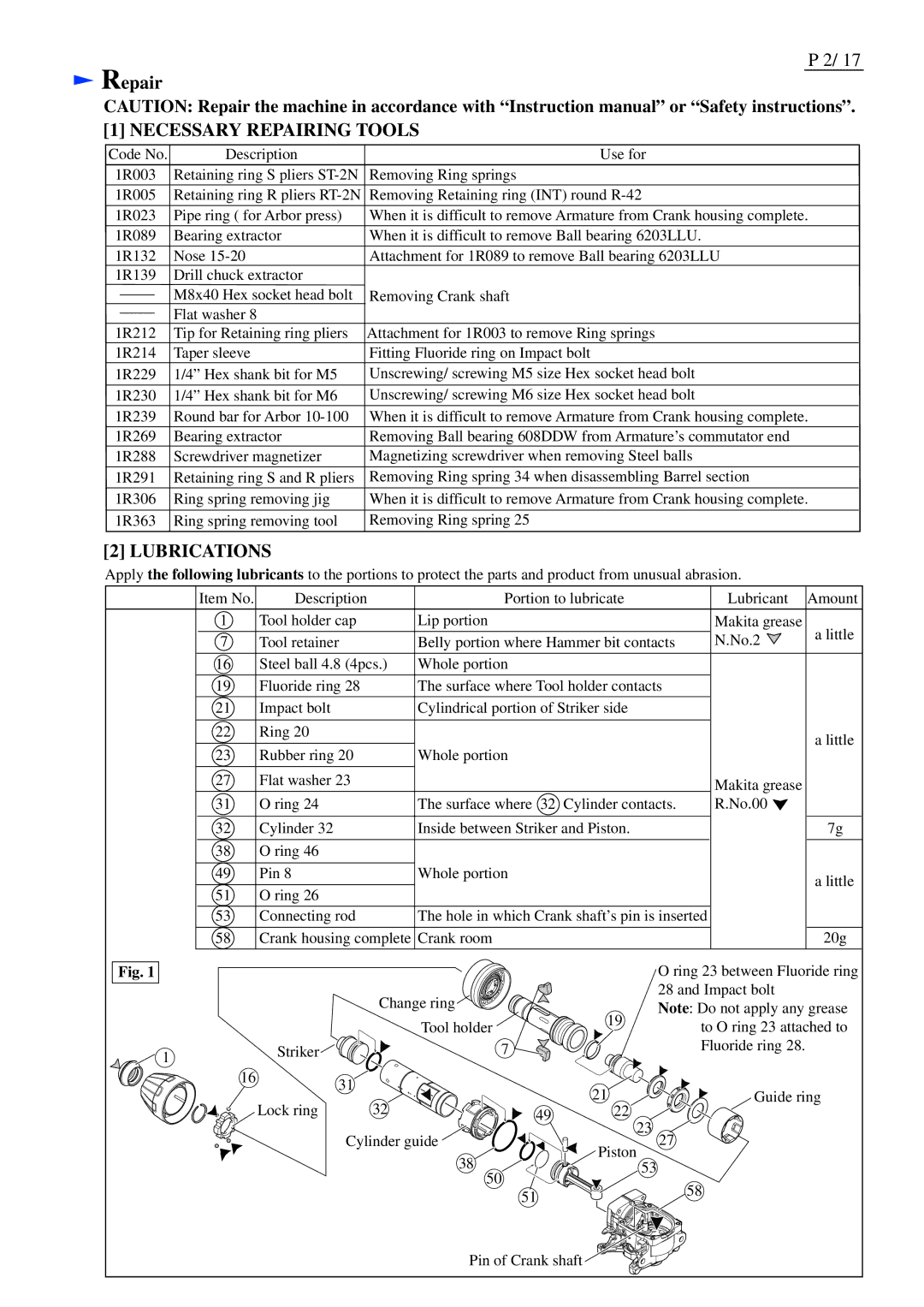
[2] LUBRICATIONS
Apply the following lubricants to the portions to protect the parts and product from unusual abrasion.
Item No. | Description |
| Portion to lubricate |
| Lubricant | Amount | |
1 | Tool holder cap |
| Lip portion |
|
| Makita grease | a little |
7 | Tool retainer |
| Belly portion where Hammer bit contacts | N.No.2 |
| ||
16 | Steel ball 4.8 (4pcs.) | Whole portion |
|
|
|
| |
19 | Fluoride ring 28 |
| The surface where Tool holder contacts |
|
| ||
21 | Impact bolt |
| Cylindrical portion of Striker side |
|
|
| |
22 | Ring 20 |
|
|
|
|
| a little |
23 | Rubber ring 20 |
| Whole portion |
|
|
| |
|
|
|
|
| |||
27 | Flat washer 23 |
|
|
|
| Makita grease |
|
|
|
|
|
|
|
| |
31 | O ring 24 |
| The surface where 32 | Cylinder contacts. | R.No.00 |
| |
32 | Cylinder 32 |
| Inside between Striker and Piston. |
|
| 7g | |
38 | O ring 46 |
|
|
|
|
|
|
49 | Pin 8 |
| Whole portion |
|
|
| a little |
51 | O ring 26 |
|
|
|
|
| |
|
|
|
|
|
| ||
53 | Connecting rod |
| The hole in which Crank shaft’s pin is inserted |
| |||
58 | Crank housing complete Crank room |
|
|
| 20g | ||
Fig. 1 |
|
|
|
| O ring 23 between Fluoride ring | ||
|
| Change ring |
| 28 and Impact bolt |
| ||
|
|
| Note: Do not apply any grease | ||||
|
|
|
| 19 | |||
|
|
| Tool holder |
| to O ring 23 attached to | ||
|
|
|
|
| |||
1 | Striker |
| 7 |
|
| Fluoride ring 28. |
|
|
|
|
|
|
|
| |
16 | 31 |
|
| 21 |
|
|
|
|
|
|
| Guide ring | |||
| Lock ring | 32 |
|
| |||
| 49 | 22 |
|
|
| ||
| Cylinder guide | 23 | 27 |
|
| ||
|
|
| 38 | Piston |
|
|
|
|
|
| 53 |
|
|
| |
|
|
| 50 |
|
| 58 |
|
|
|
| 51 |
|
|
| |
|
|
|
|
|
|
| |
|
|
| Pin of Crank shaft |
|
|
| |