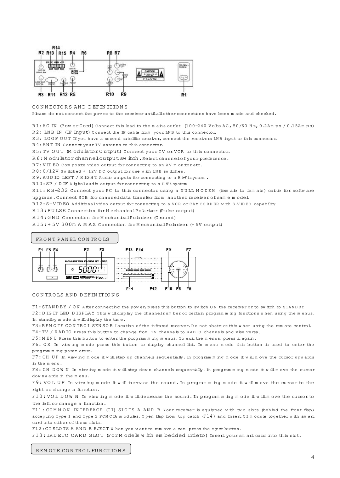
CONNECTORS AND DEFINITIONS

Please do not connect the power to the receiver until all other connections have been made and checked.

R1: AC IN (Power Cord) Connect this lead to the mains outlet (100-240 Volts AC, 50/60 Hz, 0.2Amps / 0.15Amps)

R2: LNB IN (IF Input) Connect the IF cable from your LNB to this connector.

R3: LOOP OUT If you have a second satellite receiver, connect the receivers LNB input to this connector.

R4: ANT IN Connect your TV antenna to this connector.

R5: TV OUT (Modulator Output) Connect your TV or VCR to this connector.

R6: Modulator channel output switch. Select channel of your preference.

R7: VIDEO Composite video output for connecting to an AV monitor etc.

R8: 0/12V Switched + 12V DC output for use with LNB switches.

R9: AUDIO LEFT / RIGHT Audio outputs for connecting to a Hi-Fi system.

R10: SP / DIF Digital audio output for connecting to a HiFi system

R11: RS-232Connect your PC to this connector using a NULL MODEM (female to female) cable for software upgrade. Connect STB for channel data transfer from another receiver of same model.

R12: S- VIDEO Additional video output for connecting to a VCR or CAMCORDER with S-VIDEO capability

R13: PULSE Connection for Mechanical Polarizer (Pulse output)

R14: GND Connection for Mechanical Polarizer (Ground)

R15: +5V 300mA MAX Connection for Mechanical Polarizer (+5V output)

FRONTFRONTPANELPANELCONNECTORSCONTROLS

CONTROLS AND DEFINITIONS

F1: STANDBY / ON After connecting the power, press this button to switch ON the receiver or to switch to STANDBY

F2: DIGIT LED DISPLAY This will display the channel number or certain programming functions when using the menus. In standby mode it will display the time.

F3: REMOTE CONTROL SENSOR Location of the infrared receiver. Do not obstruct this when using the remote control.

F4: TV / RADIO Press this button to change from TV channels to RADIO channels and vise versa.

F5: MENU Press this button to enter the programming menus. To exit the menus, press it again.

F6: OK In viewing mode press this button to display channel list. In menu mode this button is used to enter the programming parameters.

F7: CH UP In viewing mode it will step up channels sequentially. In programming mode it will move the cursor upwards in the menu.

F8: CH DOWN In viewing mode it will step down channels sequentially. In programming mode it will move the cursor downwards in the menu.

F9: VOL UP In viewing mode it will increase the sound. In programming mode it will move the cursor to the right or change a function.

F10: VOL DOWN In viewing mode it will decrease the sound. In programming mode it will move the cursor to the left or change a function.

F11: COMMON INTERFACE (CI) SLOTS A AND B Your receiver is equipped with two slots (behind the front flap) accepting Type 1 and Type 2 PCMCIA modules. Open flap from top catch (F14) and Insert CI module together with smart card into either of these slots.

F12: CI SLOTS A AND B EJECT When you want to remove a cam press the eject button.

F13: IRDETO CARD SLOT (For Models with embedded Irdeto) Insert your smart card into this slot.

REMOTE CONTROL FUNCTIONS

4

Page 4
Image 4
Manhattan Computer Products ST 250 instruction manual Connectors and Definitions, Remote Control Functions

ST 250 specifications

The Manhattan Computer Products ST 250 is a versatile and compact device designed to meet the demands of today's tech-savvy users. With an emphasis on performance and user-friendliness, this device integrates advanced technology and refined features into a single, efficient package.

One of the standout features of the ST 250 is its robust processing power. Equipped with a powerful, energy-efficient CPU, the device can handle demanding applications, multitasking, and complex computations with ease. This makes it suitable for both casual users and professionals who require reliable performance for tasks such as data analysis, graphic design, or software development.

Connectivity is crucial in today’s digital landscape, and the ST 250 excels in this area. It includes multiple USB ports, HDMI output, and an array of contemporary connection options, ensuring compatibility with various peripherals and external devices. Furthermore, its built-in Wi-Fi and Bluetooth capabilities provide seamless wireless interactions, making it easy to connect to the Internet or sync with other devices.

The ST 250 also features a user-friendly interface, characterized by its responsive display and intuitive navigation options. This makes it accessible for users of all skill levels, ensuring that even those who may not be tech-savvy can operate the device with minimal guidance. Additionally, the device’s compact form factor allows it to fit neatly in any workspace, making it a perfect solution for environments where space is at a premium.

Storage is another essential aspect of the ST 250. It offers ample storage options, ranging from SSDs for speed and reliability to larger HDDs for users needing more capacity. This flexibility ensures that users can choose the configuration that best meets their needs, whether prioritizing speed or storage capacity.

Durability is key for any electronic device, and Manhattan Computer Products has incorporated high-quality materials and construction into the ST 250. This ensures longevity and reliability, allowing users to depend on the device for years without significant degradation in performance.

In summary, the Manhattan Computer Products ST 250 combines powerful processing capabilities, extensive connectivity options, user-friendly design, versatile storage configurations, and durable construction. This makes it an excellent choice for individuals and businesses looking for a dependable and efficient computing solution. Whether for daily tasks, creative projects, or business operations, the ST 250 delivers the reliability and performance demanded by modern users.