ENGLISH |
| INSTALLATION | ||||||||||||
|
|
|
|
|
|
|
|
|
|
|
|
|
| |
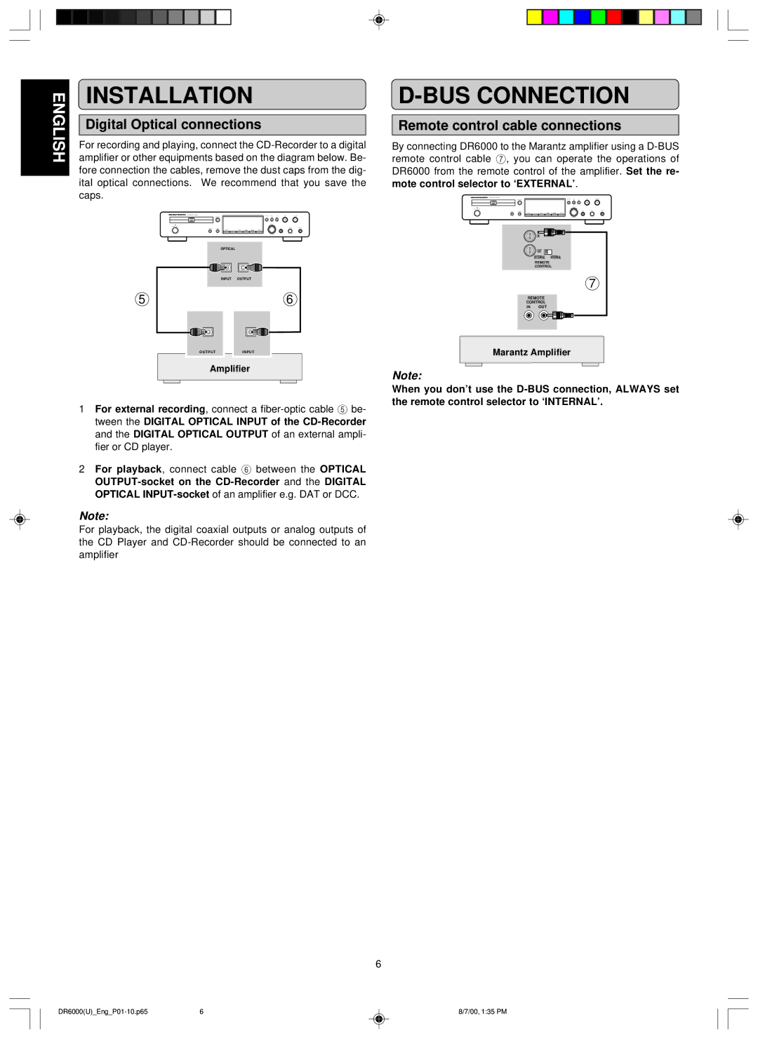
| amplifier or other equipments based on the diagram below. Be- | |||||||||||||
|
| Digital Optical connections | ||||||||||||
|
| For recording and playing, connect the | ||||||||||||
|
| fore connection the cables, remove the dust caps from the dig- | ||||||||||||
|
| ital optical connections. We recommend that you save the | ||||||||||||
|
| caps. | ||||||||||||
|
|
|
|
|
|
|
|
|
|
|
|
|
|
|
|
|
|
|
|
|
|
|
|
|
|
|
|
|
|
|
|
|
|
|
|
|
|
|
|
|
|
|
|
|
|
|
|
|
|
|
|
|
|
|
|
|
|
|
|
OPTICAL |
|
INPUT | OUTPUT |
5 | 6 |
O U T P U T | I N P U T |
Amplifier | |
1For external recording, connect a
2For playback, connect cable 6 between the OPTICAL
Note:
For playback, the digital coaxial outputs or analog outputs of the CD Player and
D-BUS CONNECTION
Remote control cable connections
By connecting DR6000 to the Marantz amplifier using a
IN
OUT
EXTERNAL INTERNAL
REMOTE
CONTROL
7
REMOTE
CONTROL
IN OUT
Marantz Amplifier
Note:
When you don’t use the
6
6 | 8/7/00, 1:35 PM |
