INSTALLATION
ASSEMBLY:
The assembled
1.Remove the carton and the unit off the skid.
2.Install the feet into the threaded mounting locations on the bottom of the unit.
3.Mount the left and right pan support racks on the mounting brackets located inside each of the cook- ing compartments.
4.Mount the drip trough to the front of the unit.
SETTING IN PLACE:
If possible, a location should be selected under an ex- haust hood which will remove small amounts of vapor emitted from the cooker during normal operation. Next, level the unit after it is placed in its final location. This is accomplished by turning the bottom part of the adjust- able feet. Using the cabinet top as a reference, obtain level adjustment
SERVICE CONNECTIONS:
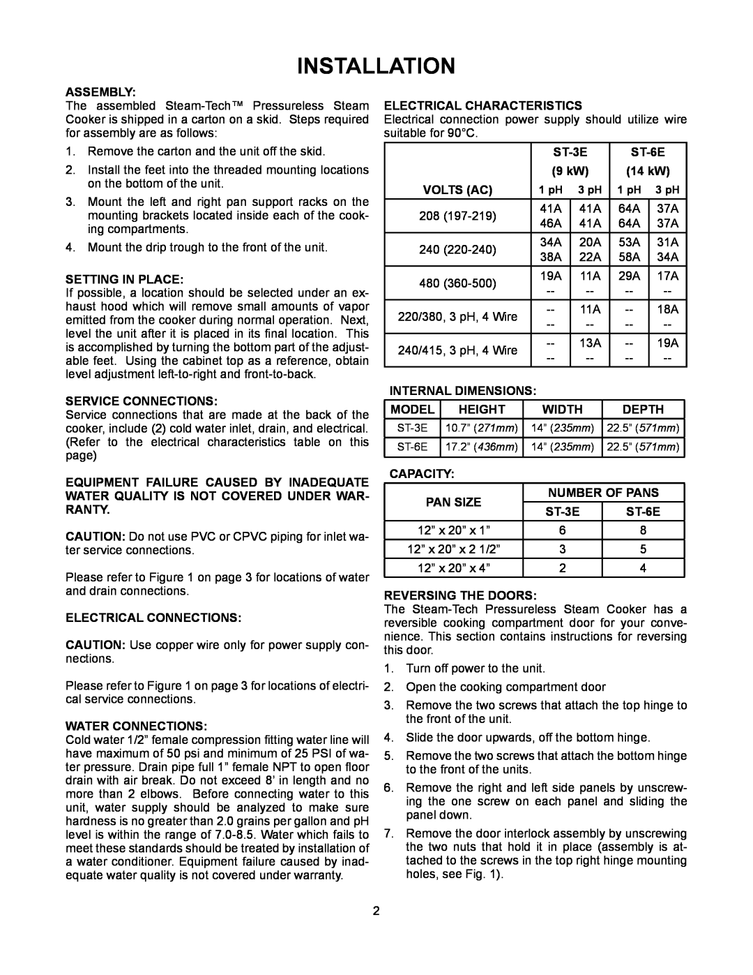
Service connections that are made at the back of the cooker, include (2) cold water inlet, drain, and electrical. (Refer to the electrical characteristics table on this page)
EQUIPMENT FAILURE CAUSED BY INADEQUATE WATER QUALITY IS NOT COVERED UNDER WAR- RANTY.
CAUTION: Do not use PVC or CPVC piping for inlet wa- ter service connections.
Please refer to Figure 1 on page 3 for locations of water and drain connections.
ELECTRICAL CONNECTIONS:
CAUTION: Use copper wire only for power supply con- nections.
Please refer to Figure 1 on page 3 for locations of electri- cal service connections.
WATER CONNECTIONS:
Cold water 1/2” female compression fitting water line will have maximum of 50 psi and minimum of 25 PSI of wa- ter pressure. Drain pipe full 1” female NPT to open floor drain with air break. Do not exceed 8’ in length and no more than 2 elbows. Before connecting water to this unit, water supply should be analyzed to make sure hardness is no greater than 2.0 grains per gallon and pH level is within the range of
Electrical Characteristics
Electrical connection power supply should utilize wire suitable for 90°C.
|
|
|
|
|
|
| |||
|
|
|
| (9 kW) |
| (14 kW) | |||
VOLTS (AC) | 1 pH | 3 pH |
| 1 pH | 3 pH | ||||
208 |
| 41A | 41A |
| 64A | 37A | |||
| 46A | 41A |
| 64A | 37A | ||||
|
|
|
|
| |||||
240 |
| 34A | 20A |
| 53A | 31A | |||
| 38A | 22A |
| 58A | 34A | ||||
|
|
|
|
| |||||
480 |
| 19A | 11A |
| 29A | 17A | |||
|
|
| |||||||
|
|
|
|
|
| ||||
220/380, 3 pH, 4 Wire | 11A |
| 18A | ||||||
|
| ||||||||
|
|
|
|
|
| ||||
240/415, 3 pH, 4 Wire | 13A |
| 19A | ||||||
|
| ||||||||
|
|
|
|
|
| ||||
INTERNAL DIMENSIONS: |
|
|
|
|
| ||||
MODEL |
| HEIGHT |
| WIDTH |
| DEPTH |
| ||
10.7” (271mm) |
| 14” (235mm) | 22.5” (571mm) |
| |||||
|
|
|
|
|
| ||||
17.2” (436mm) |
| 14” (235mm) | 22.5” (571mm) |
| |||||
|
|
|
|
|
|
|
|
|
|
CAPACITY: |
|
|
|
|
|
|
|
| |
PAN SIZE |
| NUMBER OF PANS |
| ||||||
|
|
| |||||||
|
|
|
|
|
| ||||
12” x 20” x 1” |
| 6 |
| 8 |
|
| |||
12” x 20” x 2 1/2” |
| 3 |
| 5 |
|
| |||
12” x 20” x 4” |
| 2 |
| 4 |
|
| |||
REVERSING THE DOORS:
The
1.Turn off power to the unit.
2.Open the cooking compartment door
3.Remove the two screws that attach the top hinge to the front of the unit.
4.Slide the door upwards, off the bottom hinge.
5.Remove the two screws that attach the bottom hinge to the front of the units.
6.Remove the right and left side panels by unscrew- ing the one screw on each panel and sliding the panel down.
7.Remove the door interlock assembly by unscrewing the two nuts that hold it in place (assembly is at- tached to the screws in the top right hinge mounting holes, see Fig. 1).
2
