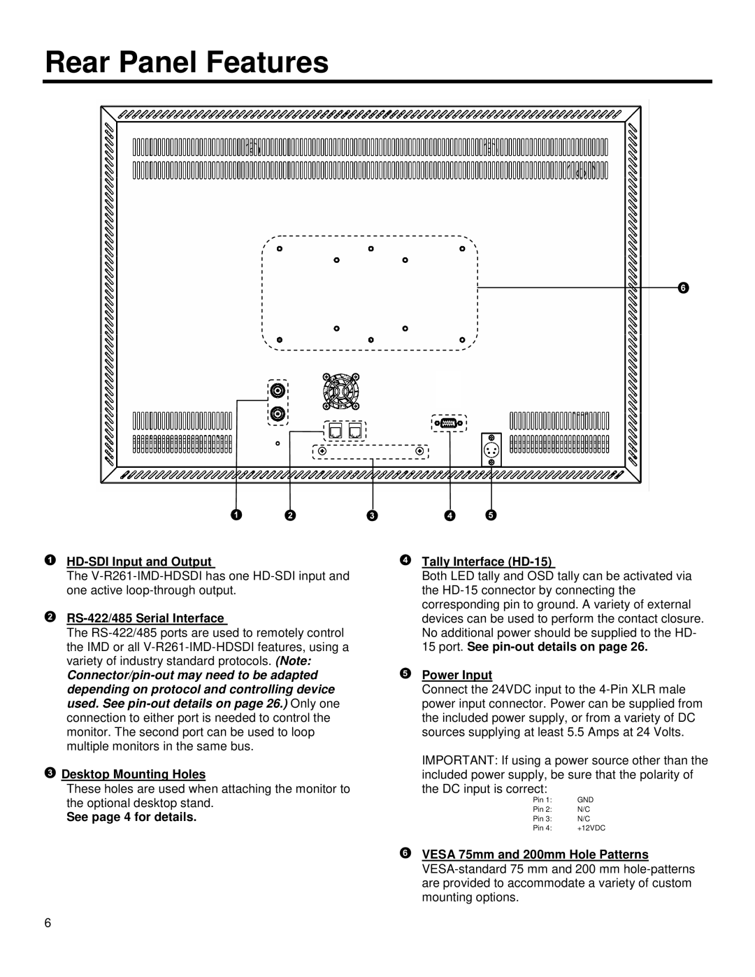
HD-SDI Input and Output
The V-R261-IMD-HDSDI has one HD-SDI input and one active loop-through output.
RS-422/485 Serial Interface
The RS-422/485 ports are used to remotely control the IMD or all V-R261-IMD-HDSDI features, using a variety of industry standard protocols. (Note:
Connector/pin-out may need to be adapted depending on protocol and controlling device used. See pin-out details on page 26.) Only one connection to either port is needed to control the monitor. The second port can be used to loop multiple monitors in the same bus.
 Desktop Mounting Holes
These holes are used when attaching the monitor to the optional desktop stand.
See page 4 for details.
6
Tally Interface (HD-15)
Both LED tally and OSD tally can be activated via the HD-15 connector by connecting the corresponding pin to ground. A variety of external devices can be used to perform the contact closure. No additional power should be supplied to the HD-
15port. See pin-out details on page 26.
Power Input
Connect the 24VDC input to the 4-Pin XLR male power input connector. Power can be supplied from the included power supply, or from a variety of DC sources supplying at least 5.5 Amps at 24 Volts.
IMPORTANT: If using a power source other than the included power supply, be sure that the polarity of the DC input is correct:
Pin 1: | GND |
Pin 2: | N/C |
Pin 3: | N/C |
Pin 4: | +12VDC |
VESA 75mm and 200mm Hole Patterns
VESA-standard 75 mm and 200 mm hole-patterns are provided to accommodate a variety of custom mounting options.