http://www.LCDRacks.com e-mail: sales@mars-cam.com
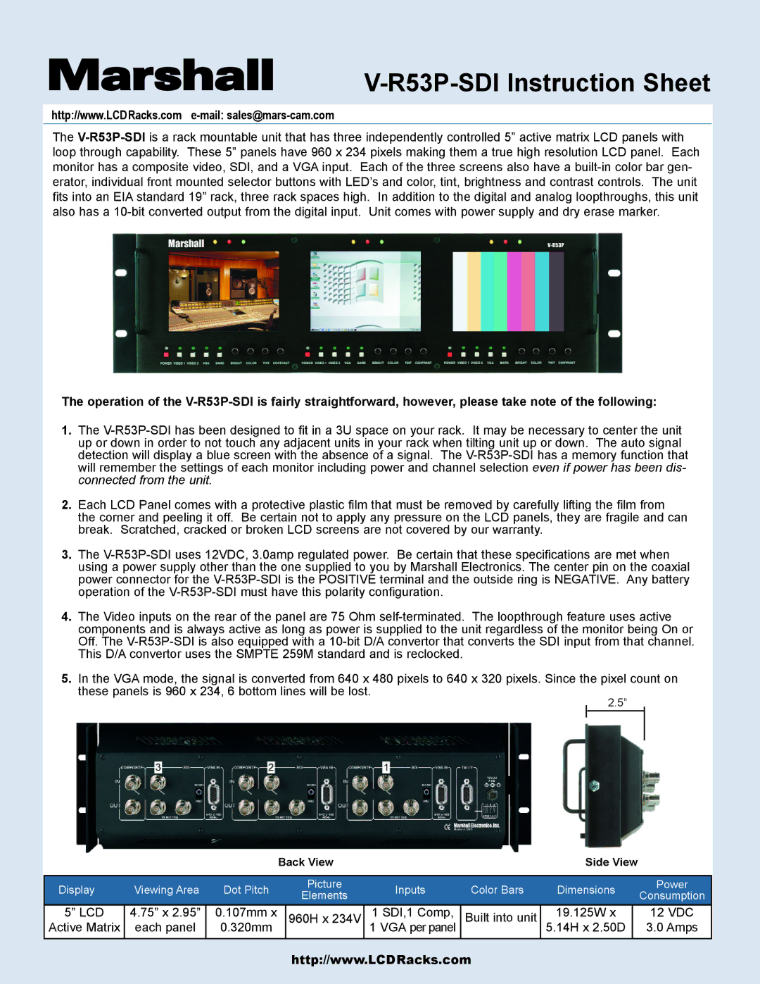
The V-R53P-SDIis a rack mountable unit that has three independently controlled 5” active matrix LCD panels with loop through capability. These 5” panels have 960 x 234 pixels making them a true high resolution LCD panel. Each monitor has a composite video, SDI, and a VGA input. Each of the three screens also have a built-in color bar gen- erator, individual front mounted selector buttons with LED’s and color, tint, brightness and contrast controls. The unit fits into an EIA standard 19” rack, three rack spaces high. In addition to the digital and analog loopthroughs, this unit also has a 10-bit converted output from the digital input. Unit comes with power supply and dry erase marker.
The operation of the V-R53P-SDI is fairly straightforward, however, please take note of the following:
1.The V-R53P-SDI has been designed to fit in a 3U space on your rack. It may be necessary to center the unit up or down in order to not touch any adjacent units in your rack when tilting unit up or down. The auto signal detection will display a blue screen with the absence of a signal. The V-R53P-SDI has a memory function that will remember the settings of each monitor including power and channel selection even if power has been dis- connected from the unit.
2.Each LCD Panel comes with a protective plastic film that must be removed by carefully lifting the film from the corner and peeling it off. Be certain not to apply any pressure on the LCD panels, they are fragile and can break. Scratched, cracked or broken LCD screens are not covered by our warranty.
3.The V-R53P-SDI uses 12VDC, 3.0amp regulated power. Be certain that these specifications are met when using a power supply other than the one supplied to you by Marshall Electronics. The center pin on the coaxial power connector for the V-R53P-SDI is the POSITIVE terminal and the outside ring is NEGATIVE. Any battery operation of the V-R53P-SDI must have this polarity configuration.
4.The Video inputs on the rear of the panel are 75 Ohm self-terminated. The loopthrough feature uses active components and is always active as long as power is supplied to the unit regardless of the monitor being On or Off. The V-R53P-SDI is also equipped with a 10-bit D/A convertor that converts the SDI input from that channel. This D/A convertor uses the SMPTE 259M standard and is reclocked.
5.In the VGA mode, the signal is converted from 640 x 480 pixels to 640 x 320 pixels. Since the pixel count on these panels is 960 x 234, 6 bottom lines will be lost.
2.5”
| | | | Back View | | | | | Side View | | |
| | | | | | | | | | | | | |
| | | | | | | | | | | | |
Display | Viewing Area | Dot Pitch | | Picture | | Inputs | Color Bars | | Dimensions | Power |
| Elements | | | Consumption |
| | | | | | | | | | |
5” LCD | 4.75” x 2.95” | 0.107mm x | | 960H x 234V | | 1 SDI,1 Comp, | Built into unit | | 19.125W x | | 12 VDC |
Active Matrix | each panel | 0.320mm | | 1 VGA per panel | 5.14H x 2.50D | | 3.0 Amps |
| | | | | | | | | | | | | |