3.After inspection, attach adjustable rear support brackets using the supplied thumbscrews and install the
Thumbscrews and |
| Attached bracket |
rear support bracket |
|
|
|
|
|
4. Connect required cables for signal input and output.
Note: All BNC connectors should be rated for 75Ω.
Note: Power must be applied to the
5.Plug the
6.Attach the twist lock Conxal power connection from
7.Completely Slide the
8.Turn on the
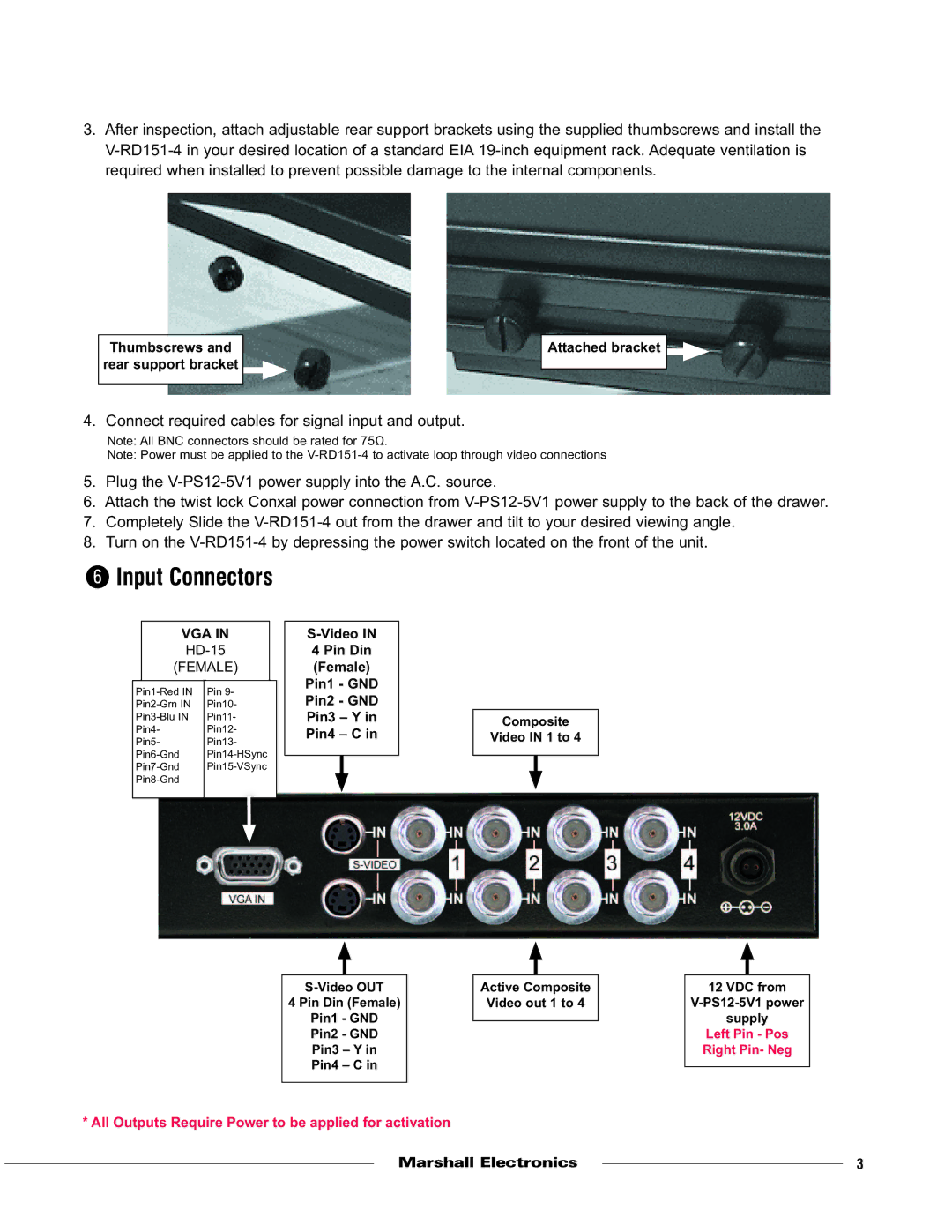
6Input Connectors
VGA IN
(FEMALE)
Pin 9- | |||
Pin10- | |||
Pin11- | |||
Pin4- | Pin12- | ||
Pin5- | Pin13- | ||
|
|
| |
|
|
|
|
S-Video IN
4 Pin Din
(Female)
Pin1 - GND
Pin2 - GND
Pin3 – Y in
Pin4 – C in
Composite
Video IN 1 to 4
| Active Composite |
| 12 VDC from | |
4 Pin Din (Female) |
| Video out 1 to 4 |
| |
Pin1 - GND |
|
|
| supply |
| ||||
Pin2 - GND |
|
|
| Left Pin - Pos |
Pin3 – Y in |
|
|
| Right Pin- Neg |
Pin4 – C in |
|
|
|
|
|
|
| ||
|
|
|
|
|
* All Outputs Require Power to be applied for activation
Marshall Electronics |
| 3 |
| ||
|
|
|