Controls and Functions
2.3
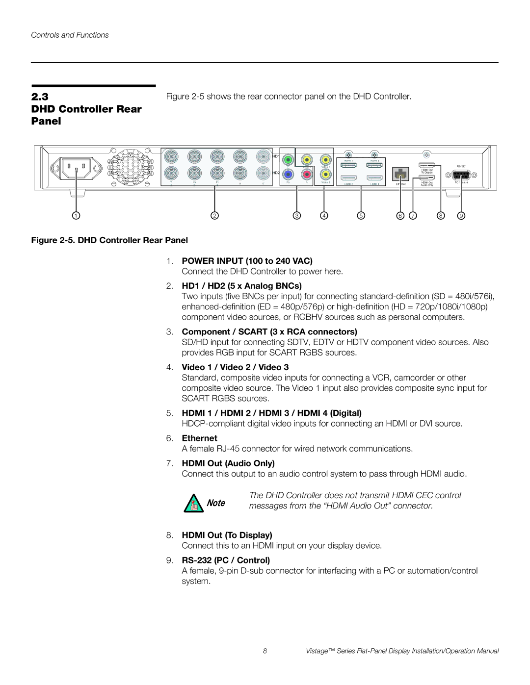
DHD Controller Rear Panel
1 | 2 | 3 | 4 | 5 | 6 | 7 | 8 | 9 |
Figure 2-5. DHD Controller Rear Panel
1.POWER INPUT (100 to 240 VAC) Connect the DHD Controller to power here.
2.HD1 / HD2 (5 x Analog BNCs)
Two inputs (five BNCs per input) for connecting
3.Component / SCART (3 x RCA connectors)
SD/HD input for connecting SDTV, EDTV or HDTV component video sources. Also provides RGB input for SCART RGBS sources.
4.Video 1 / Video 2 / Video 3
Standard, composite video inputs for connecting a VCR, camcorder or other composite video source. The Video 1 input also provides composite sync input for SCART RGBS sources.
5.HDMI 1 / HDMI 2 / HDMI 3 / HDMI 4 (Digital)
6.Ethernet
A female
7.HDMI Out (Audio Only)
Connect this output to an audio control system to pass through HDMI audio.
Note | The DHD Controller does not transmit HDMI CEC control |
messages from the “HDMI Audio Out” connector. |
8.HDMI Out (To Display)
Connect this to an HDMI input on your display device.
9.RS-232 (PC / Control)
A female,
8 | Vistage™ Series |
