Digital Congress Network DCN
Page
Bosch Security Systems 04-2003 3922 988 43318 en
2003
Important Safeguards
Manual is divided into the following chapters
Environmental Conditions and Maintenance
About this Manual
This page has been left blank intentionally
Table of Contents
Chapter DCN Camera Control
Chapter DCN Control using Personal Computers
Chapter Installation Techniques
Chapter
System Set-up & Operation 11-1
Environmental Conditions and Maintenance
Chapter Technical Data
LBB 3537/00 and LBB 3537/50 Microphone with
13.3.2
13-4
13-5
Central Control Equipment
Introduction Digital Congress Network DCN
Contribution equipment
Full range of DCN equipment includes
Interpretation
Information display equipment
Application software packages
Language Distribution
Praedic
Installation equipment
DCN’s System Philosophy
Quick reference to DCN’s functions
Voting
Attendance Registration and Access Control
System Installation software
Intercom
DCN Open Interface
Multi-CCU Control
DCN Startup
DCN
Glossary of Abbreviations and Acronyms
CCU
PCF
This page has been left blank intentionally
Active units
Contribution Equipment
Table-top Contribution units
Passive units no contribution, only in FM section
Chairman unit
Delegate unit
4 ‘Microphone Only’ Function
Interpreter desk
LBB 3530/xx and LBB 3531/xx Delegate Discussion Unit
Controls and Indicators FIG
Controls and Indicators -3and FIG
LBB 3533/xx and LBB 3534/xx Chairman Discussion Unit
Adjustment setting discussion units
Solder spot J1
Mounting discussion units FIG
Key to symbols FIG
Interconnection details discussion units
Rear view Discussion unit Trunk Cable Splitter LBB 4114/00
Rear, side and under views -9and FIG
LBB 3547/00 Chairman Conference Unit Concentus
Next unit
Rear Microphone Release screw
Under
To previous unit
Functionality Solder spots
Adjustment setting conference Concentus units
Solder spot Intercom handset connector
LBB 3555/00 Intercom handset
Controls and Indicators
LBB 3549/00, LBB 3549/50 Pluggable Microphones
Type number description
Method 1 mounting into a metal surface
Flush-mounted Contribution equipment
Mounting
Method 2 mounting into a wooden surface
LBB 3535/00 Dual Audio Interface unit
LBB 3535/00 Dual Audio Interface unit
Function
Floor stand or Podium Microphones -20and FIG
Flush Mounting Solutions
Flush mounted solution No.2 serving a chairman position FIG
Connection details 8-pole 262 DIN-socket
20 floor stand microphone
Cable terminated with an 8-pole 262 DIN-type plug
LBB 3536/00, /10 Hand-microphones
LBB 3540/15 Multi-purpose connection unit
LBB 3536/00, /10 Hand-microphones
LBB 3540/15 Multi-purpose connection unit
Solder spot J03 Open default
Minute of remaining speech time J02
From next unit
Flush mounted solution No.6 delegate position FIG
LBB 3540/15 Multi-purpose connection unit LBB 3537/00
LBB 3537/xx
LBB 3538/00 LBB 3537/xx Landscape
LBB 3538/00 Landscape
See Note
Applicable to solution No.8
Or pluggable
Type number description
LBB 3537/20 Pluggable Microphone control panel
Microphone on indicator red LED ‘Priority’ key
LBB 3537/10 Chairman microphone with control panel
LBB 3537/10 Chairman microphone with control panel
LBB 3541/00 FM Delegate Voting Control panel
Controls, Indicators and Interconnection FIG
LBB 3538/00 FM Loudspeaker panel
6.5 ft. long cable terminated with a 3.5 mm stereo jackplug
Assigned Delegate
LBB 4159/00 Set of 100 Chip Cards
Controls and Indicators see FIG
LBB 3543/15 FM Chip-Card Reader
Card specification
Position of the DIP switches
LBB 4157/00 Chip Card Encoder
Positioning the Encoder
Installing the External Encoder see FIG
Serial Cable Power supply cable
Interconnection FIG LBB 3524/00
LBB 3524/10 and LBB 3526/10 FIG
Open
Auto Switch-Off function
Solder spot J70 to set repeat/single-step volume-up control
Closed
‘snap-off’ lugs
LBB 3527/00 Table top housing
LBB 3539/00 Blanking panels
LBB 3527/00 Table top housing
Interpreter desk LBB 3520/10
Interpretation Equipment
LBB 3520/10 Interpreter desk with back-lighting LC-display
For onward interpretation
Incoming Channel Controls
Controls and Indicators LBB 3520/10 see FIG
Loudspeaker Controls
Outgoing Channel Controls
Side view LBB 3520/10
Screws a
Key to Symbols
Removal cable guide -3 Interpreter desk LBB 3520/10
Interpreter desk LBB 3520/10
LBB 3513/00 Analog Audio Input/output Module
This page has been left blank intentionally
Stand-alone systems
Central Control Equipment
Introduction Central control equipment
PC control
LBB 3500/35, LBB 3500/35D Multi Central Control Unit
LBB 3500/05, LBB 3500/05D Basic Central Control Unit
LBB 3500/15, LBB 3500/15D Central Control Unit
Internal view
Front panel
Rear panel
TCB
Removal top cover
CCU Mains voltage and adjustment
CCU Mains cable, plug and socket
CCU Mains fuse rating
CCU Trunk Communication Board TCB4
Installation
DIP-switch S14
X14 Location
Tone on default
S9 DIP-switch settings
Jumper settings
X13
CU Protocol and Serial Port settings
Multi-CCU card
S12 on
6 5 4 3 2 S12 on
Example Setting Address
6 5 4 3 2 S12 on
Connecting peripheral equipment to the CCU
Connecting peripheral equipment to the CCU
Signal +
Symmetrical
CCU Audio Routing Modes
MIX-MINUS mode FIG
Switch-2 Switch-3 Mode
DCN System a
REC.
Audio Routing Insertion mode FIG
REC. UIT
Mixer
LBB 4106/00, LBB 4106/00D
Extension power supply unit
LBB 4106/00, LBB 4106/00D Extension power supply unit
Mains connection
5 ft. D-version 2.5 m 8.2 ft. long included
Cinch Connector
Audio output cinch-type sockets Asymmetrical Signal Earth
Rack Mounting DCN Control Units
12 19 Rack Mounting DCN Control Units
Rack mounting brackets Supplied with the CCU
DCN Control PC For Windows 95
DCN Control using Personal Computers
Minimum Software and hardware requirements
For NT 4.0, Windows 2000 or Windows XP Professional
Jumpers
Cable and connectors see -1and FIG
LBB 3510/00 PC Network card
LBB 3510/00 layout Network card
Interconnections PC Network card
Installing PC-Network card
Windows and DCN Software modules
Interconnection Personal Computer PC
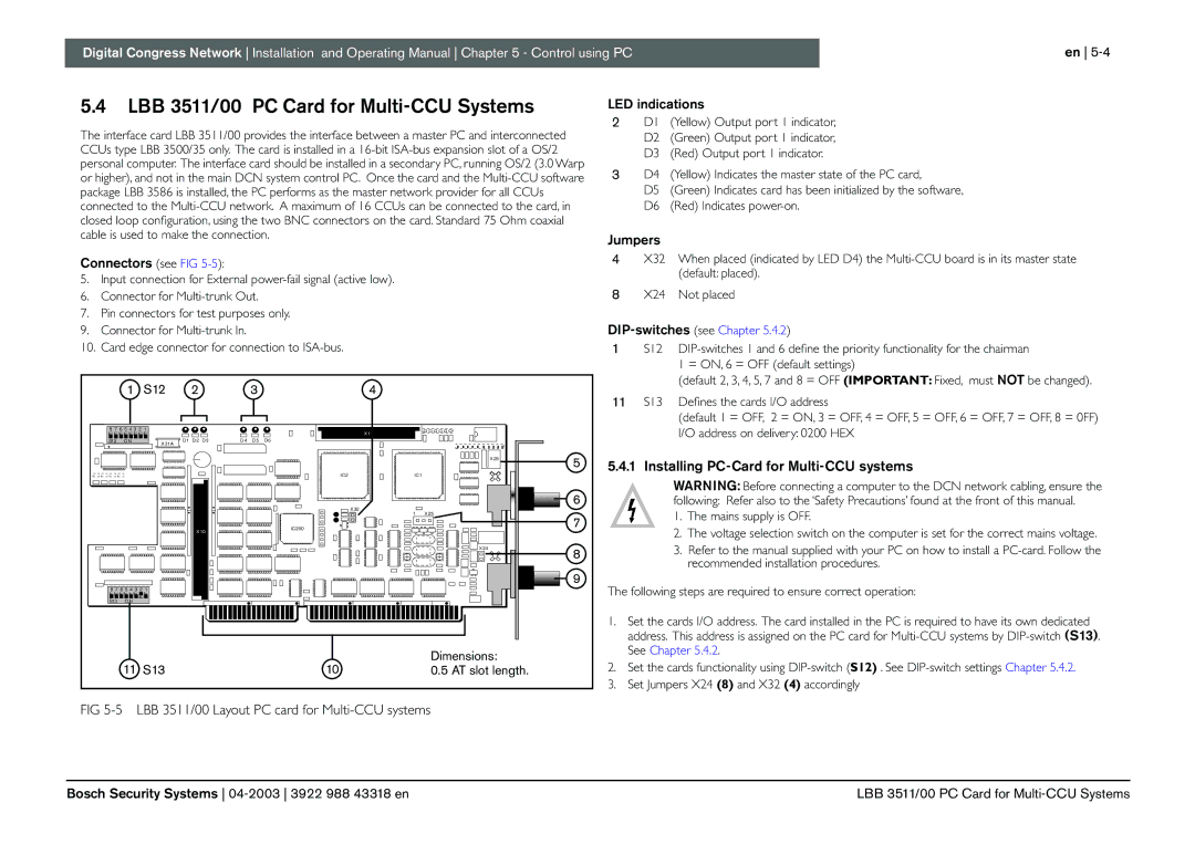
Installing PC-Card for Multi-CCU systems
Connectors see FIG
DIP-switches see Chapter
LBB 3511/00 PC Card for Multi-CCU Systems
DIP-SWITCH S13
LBB 3511/00 DIP-switch S12 and S13 settings
Address 0200HEX default Address 0280HEX S13
Address 0140HEX Address 0100HEX S13
Connection PC to CCU
Connection PC to CCU
COM
‘wire-to-wire’
Control PC
Master CCU PC Master CCU PC requirements Control PC
Control PC requirements
‘DIRECT’ DCN PC control
LBB 3511/00 OS/2 version 3.0 Warp or higher
PC Network System
Software configuration Master CCU PC OS/2 Serial Ports 1
Ccupc
Ccucfg file settings
Master CCU PC
For COM and LPT cable connections, refer to FIG
None Flow control =
Mode Bit standard Baud-rate 9600
Parity None
Done in the dcn.ini file located in the ‘Window
Connecting Peripheral devices
CHIP-CARD Encoder
This page has been left blank intentionally
DCN Camera Control
Allegiant Video Switcher
Allegiant Switcher Control Keyboards
Cameras and Monitors
Range of Bosch Allegiant Video Switchers
Requirements
DCN Allegiant Video SWITCHING/CONTROL Equipment
4.4 4. PC COM Port settings
Installation of a Single CCU
Installation of a Multi-CCU
Set-up Camera configuration
Installation of Camera Control software on the temporary PC
Other fixed settings are
Communication settings
Databits Parity None Stopbits
Camera and Monitor
Direct Camera Control
Virtual Keyboard
DCN PC controlled system with single CCU
Set-up Camera Configuraion
Stand-alone DCN system
Using microphone activity for video switching
Switching options using a personal computer
Key to symbols
Data format for RS232 communication
Trunk-line connector
DCN Installation accessories
Introduction Installation accessories
Trunk-line LBB 4114/00
LBB 4115/00 Tap-off Unit
Key to symbols see FIG
LBB 4114/00 Trunk-cable splitter
Interconnection see FIG
Extension cable assemblies LBB 4116/xx
Cable assemblies and connectors
Installation cable LBB 4116/00
Cable Connection details
LBB 4117/00 Termination plug for DCN Cable
Connectors
LBB 4117/00 Set of 25 cable locking clamps
LBB 3512/00 Data Distribution Board Electrical data
Information Displays
LBB 3512/00 Data Distribution Board
LBB 3512/00 Data Distribution Board
Electrical requirements
Data Distribution Board 9-pin Sub-D connector
Connectors, Controls and Indicators see FIG
Parallel input and output connections
Board Address setting
Data Format Specifications RS232 Output
Application
To DCN system LBB 3512/00
Installing Data Distribution board LBB 3512/00
Connecting Hall Displays to the DCN System
Running only with software-modules on Control-PC
To other video displays
Client PC
From DCN PC
This page has been left blank intentionally
Telos Digital Telephone Interface
DCN Peripheral Equipment
Introduction Peripheral Equipment
Bosch Security Systems 04-2003 3922 988 43318 en
System design fundamentals
Installation Techniques
Introduction Installation Techniques
10.2 Power Handling Capacity
Power Handling Capacities
LBB 3508 Audio Media Interface Unit
Trunk outlets and Tap-offs
Tap-off limitations
Overload indication
Table-top units
Flush mounted units
System overload
System limits FIG
Using Tap-Off unit LBB 4115/00
Maximum cable lengths using Trunk-outlets and/or Tap-offs
LBB 4115/00 Tap-off unit limitations
Calculation Method
10 m 32.8 ft 20 m 65.6 ft m 164 ft
Concentus
System Using
Discussion Units
Units
PCF
Graph reference examples
CON
Active contribution units include
Control Capacity
Stand-alone Systems
Passive distribution units include
Centralised System
14 Unit layout possibilities using trunk-splitters
15 Typical system interconnection
DE-CENTRALISED System
Computer Based Systems
17 Connection using PC Network card
IN-DIRECT Connection using PC Network card LBB 3510/0
Direct Connection from CCU to PC
LBB 3500/15 or /35
PC system for 270 PCF
PC System for 270 PCF
PCF ≤ 180 max PC Network Card LBB 3510/00 LBB 3508/00
Software requirements on the PC’s Server PC
PC Network System
Ethernet requirements
Client PC
Multi-CCU system
19 Typical solution providing more control positions
Installing the Multi-CCU software package LBB 3586/00
Multi-CCU and PC interconnection
Single CCU System LBB 3500/15 and LBB 3500/35 FIG
Remote Controller
20 Multi-CCU configuration and connection
Multi- CCU System FIG
Interconnecting Interpretation Equipment
Interconnecting Interpreter desks
Language Distribution Equipment
Wired
Wireless
Introduction
Flush Mounted Language Distribution
Wired Language Distribution
Table Top Language Distribution
26 Table-top language distribution
Integrus digital Infra red system
This page has been left blank intentionally
Initializing a stand-alone system FIG
System Set-up & Operation
Introduction
De-initializing CCU Initializing a PC-based system
Setting up a stand-alone system
Downloading Control PC-software
Maintenance Menu
Multi-CCU Set-up for the first-time
Multi-CCU Set-up for the first-time
To set system default Language
To set system Intercom Operator Position
Equalizer function
How to Set System Volume/gain level
Sound Management
To Equalize the system proceed as follows
Voting modes
Intercom Facilities
LBB 3530/xx LBB 3531/xx LBB 3533/xx LBB 3534/xx
Delegate/Chairman unit operation Conference units only
LBB 3544/00 LBB 3545/00 LBB 3546/00 LBB 3547/00
Located at the left side
Microphone on ID Chip-card reader Indicator
Microphone functions Selection Microphone headset
Response applicable to all delegate units
LBB 3546/00 unit with display
Message PC controlled systems only
LBB 3544/00, LBB 3545/00 units without display
Intercom LED status
LED status during voting procedure
Key to voting symbols
Operation Chairman Unit LBB 3547/00
Microphone functions Selection
Microphones from
Priority key
Priority key Active key Microphone status indication
Press softkey
XX = Defines number of participants
Priority function LBB 3533/xx and LBB 3534/xx only
Operating Delegate/Chairman units Discussion units only
For unit description see .2 and Chapter Microphone
Language channel selection LBB 3531/.. and LBB 3534/.. only
Interpretation
LBB 3520/10
LC-display
Normal operation floor active
Incoming Floor switch and Auto-relay
Operating the Interpreter Desk
Incoming Channel Selection
11 Outgoing Channel Selection
Outgoing Channel Selection
Interpreter desk Listening
Output
Microphone operation
Typical Displays showing outgoing channels
Engaged LEDs
Call
Programming the Interpreter desk
Entering the desks programming mode
Menu Programming procedures
Menu a. Select Display Programming Language
Menu b. Select Booth Number
Procedure
Menu c. Select Desk Number Within a Booth
Menu d. Select Number of Channels
Refer to Step
Menu e. Select language list
Menu f. Select language for channels
Language and Abbreviations
Menu g. Select outgoing channel via A-output
Menu j. Select number of auto-relay booths
Menu h. Select outgoing channels via B-output
End Programming session
Menu k. Select auto-relay booth
Menu l. Select microphone locks between booths
This page has been left blank intentionally
Public areas
Environmental Conditions Maintenance
System
Technical rooms
Interpreter booths
Interpreter booths
Cleaning
Ventilation
Metric/imperial Conversion
Technical Data
Mechanical data
LBB 3500/.. Central Control Units
LBB 3508/00 and LBB 3508 D Audio Media Interface Unit
LBB 4106/00 and LBB 4106/00 D Extension Power Supply Unit
Weight
Table-top units 13.2.1 Conference Units
Channel Selector Housing
LBB 3527/00 Table-top housing for FM loudspeaker panel
LBB 3525/00 Channel Selector housing
LBB 3536/xx Hand microphones
LBB 3526/10 FM Electronic Channel Selector Panel
Surface using the units screw mounting facilities
Flush Mounted Equipment
Electronic Channel Selector Panel
LBB 3537/10 FM Chairman Priority Control Panel
LBB 3538/00 FM Loudspeaker panel
Flush-mounted Microphone control panel
Flush-mounted Delegate/Chairman Voting Control Panel
LBB 3540/15 Multi-purpose Connection Unit
LBB 3541/00 Delegate Voting Control Panel
Screws provided
12 Flush-mounted Chip Card Reader
Installation Accessories
LBB 3543/15 Chip Card Reader
LBB 4114/00Trunk Cable Splitter LBB 4115/00 Tap-off Unit
13.5.1 Microphones General
Headphones
13.5 Electrical data
Transmission links
Combined units
System Electrical and Electro-acoustical characteristics
Power consumption nominal
System environmental conditions
System limitations
Connection details
Jack-plug
Pole D-type connector PC Interface
Concentus units
Interpreter desk headset socket DIN-type
+ = Audio outputs
Available Audio Down Link Channels
Systems with a PC
R4995.52X
146
R700.5 R995.5
24.5