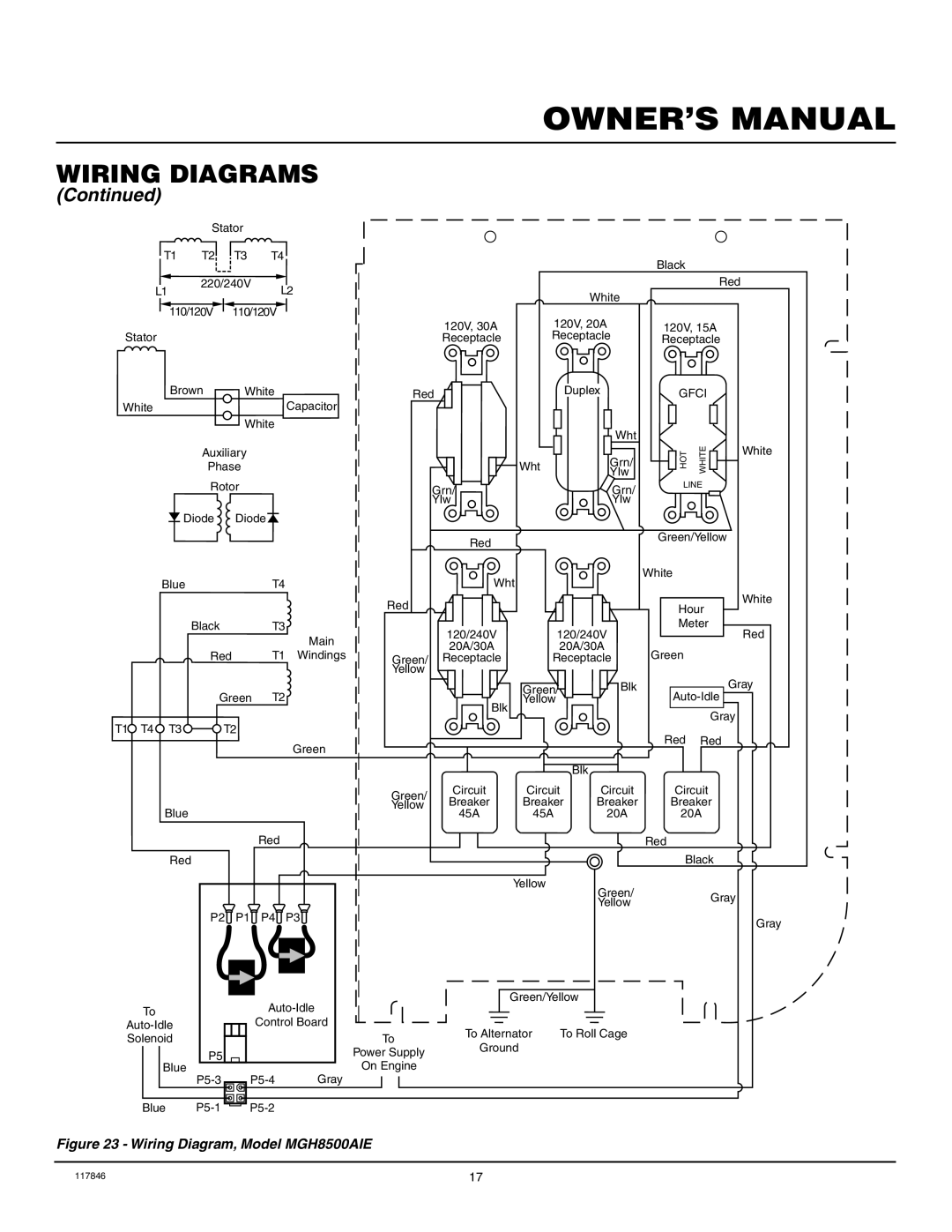
MGH8500AIE, MGH10000C specifications
The Master Lock MGH10000C and MGH8500AIE are two of the most advanced padlocks offered by Master Lock, a company renowned for its commitment to security and innovation. Both models feature cutting-edge technologies designed to enhance security while providing user-friendly functionalities.The MGH10000C is particularly notable for its Bluetooth connectivity, allowing users to manage access via a smartphone application. This feature makes it easy to lock or unlock the padlock without the need for traditional keys or combinations. The app also enables users to grant temporary access to others, making it ideal for shared spaces like gyms, offices, or home environments. The padlock's robust construction includes a durable zinc body and a hardened steel shackle, ensuring resistance against cutting and prying.
In contrast, the MGH8500AIE offers an integrated fingerprint scanner that can store up to 10 different fingerprints. This biometric feature makes it a convenient choice for users who prefer quick access. The MGH8500AIE’s compact design and weather-resistant construction make it suitable for both indoor and outdoor use, providing reliability in various environments. The one-touch access feature allows users to unlock the padlock with just a finger, making it efficient for daily use.
Both models are designed with user security in mind. The MGH10000C includes a tamper alert system that sends notifications if unauthorized access attempts are made, providing peace of mind. On the other hand, the MGH8500AIE is equipped with a low-battery indicator that reminds users to replace the batteries before they run out, preventing lockouts.
In terms of power supply, the MGH10000C operates on a rechargeable battery, which can last for several months on a single charge, while the MGH8500AIE uses replaceable batteries designed for long-life performance.
Overall, whether choosing the smartphone-enabled Master Lock MGH10000C or the biometric MGH8500AIE, users benefit from advanced security features, exceptional durability, and convenient access methods. These padlocks stand as prime examples of how technology can enhance everyday security solutions, making them a worthy investment for anyone seeking reliable protection for their belongings.

