or,
2.If running DOS or Windows 3.x, configure the modem using the included modem driver. Instructions for installing this driver are included in the text file called README.1ST on the Windows 95 driver disk.
The README.1ST file can be viewed by loading it into any wordprocessor or any text editor (i.e. DOS EDIT, NOTEPAD). It may also be viewed by using the DOS TYPE command. Refer to your word processor manual or DOS/Windows references for information on loading text files.
2.3 Hardware Installation
Installation of this modem requires opening and manipulat- ing your PC. Exercise caution at all times when working with AC powered and
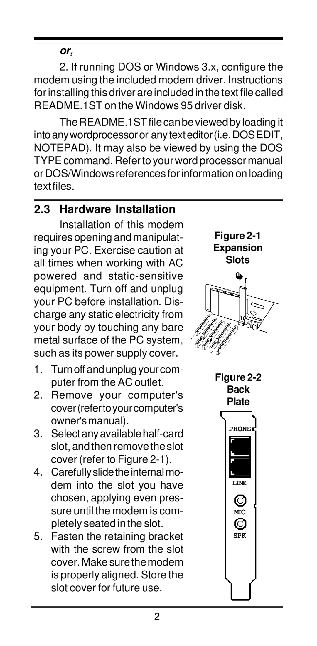
Figure
Expansion
Slots
1.Turn off and unplug your com- puter from the AC outlet.
2.Remove your computer's cover(refertoyourcomputer's owner's manual).
3.Select any available
4.Carefully slide the internal mo- dem into the slot you have chosen, applying even pres- sure until the modem is com- pletely seated in the slot.
5.Fasten the retaining bracket with the screw from the slot cover. Make sure the modem is properly aligned. Store the slot cover for future use.
Figure
Back
Plate
PHONE
LINE
MIC
SPK
2
