Installation
3.4.1DC Power (J1, Section A)
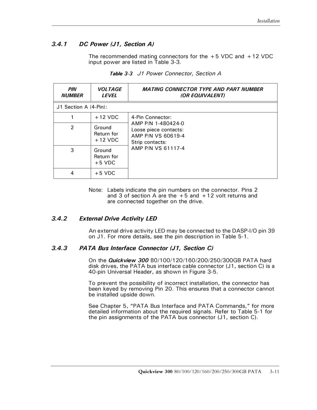
The recommended mating connectors for the +5 VDC and +12 VDC input power are listed in Table
Table 3-3 J1 Power Connector, Section A
PIN | VOLTAGE | MATING CONNECTOR TYPE AND PART NUMBER | |
NUMBER | LEVEL | (OR EQUIVALENT) | |
|
|
| |
|
| ||
J1 Section A |
| ||
|
|
| |
1 | +12 VDC | ||
|
| AMP P/N | |
2 | Ground | ||
Loose piece contacts: | |||
| Return for | ||
| AMP P/N VS | ||
| +12 VDC | ||
| Strip contacts: | ||
|
| ||
3 | Ground | AMP P/N VS | |
| |||
| Return for |
| |
| +5 VDC |
| |
|
|
| |
4 | +5 VDC |
| |
|
|
| |
Note: Labels indicate the pin numbers on the connector. Pins 2 and 3 of section A are the +5 and +12 volt returns and are connected together on the drive.
3.4.2External Drive Activity LED
An external drive activity LED may be connected to the
3.4.3PATA Bus Interface Connector (J1, Section C)
On the Quickview 300 80/100/120/160/200/250/300GB PATA hard disk drives, the PATA bus interface cable connector (J1, section C) is a
To prevent the possibility of incorrect installation, the connector has been keyed by removing Pin 20. This ensures that a connector cannot be installed upside down.
See Chapter 5, “PATA Bus Interface and PATA Commands,” for more detailed information about the required signals. Refer to Table
Quickview 300 80/100/120/160/200/250/300GB PATA |