BACK PANEL
DVR
|
|
| 9 | 8 |
|
|
|
|
|
|
| LOOP | MAIN |
|
|
|
|
|
|
|
|
| IN | OUT |
| |
|
|
|
|
|
|
| ||
|
|
|
|
|
|
|
| RISK OF ELECTRIC SHOCK |
|
|
|
|
|
|
|
| DO NOT OPEN |
|
| HI | INPUT |
| 1 | 3 | R | WARNING: TO REDUCE THE RISK OF ELECTRIC SHOCK, |
|
|
|
|
|
|
| DO NOT REMOVE COVER (OR BACK). | |
|
|
|
|
|
|
|
| NO |
|
|
|
|
|
|
|
| REFER SERVICING TO QUALIFIED |
|
|
|
|
|
|
|
| SERVICE PERSONNEL. |
POWER | EXTERNAL I/O | 75Ω |
| CALL | 2 | 4 | L |
|
|
|
|
|
|
| |||
1 | 2 | 3 | 4 | 5 |
| 6 | 7 |
|
|
|
|
|
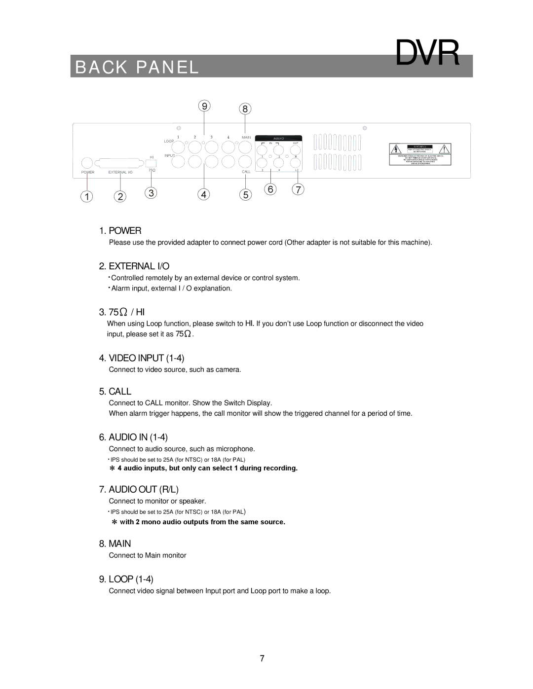
1. POWER
Please use the provided adapter to connect power cord (Other adapter is not suitable for this machine).
2. EXTERNAL I/O
‧Controlled remotely by an external device or control system. ‧Alarm input, external I / O explanation.
3. 75Ω / HI
When using Loop function, please switch to HI. If you don’t use Loop function or disconnect the video input, please set it as 75Ω.
4. VIDEO INPUT
Connect to video source, such as camera.
5. CALL
Connect to CALL monitor. Show the Switch Display.
When alarm trigger happens, the call monitor will show the triggered channel for a period of time.
6. AUDIO IN (1-4)
Connect to audio source, such as microphone.
‧IPS should be set to 25A (for NTSC) or 18A (for PAL)
✻ 4 audio inputs, but only can select 1 during recording.
7.AUDIO OUT (R/L)
Connect to monitor or speaker.
‧IPS should be set to 25A (for NTSC) or 18A (for PAL)
✻with 2 mono audio outputs from the same source.
8.MAIN
Connect to Main monitor
9. LOOP
Connect video signal between Input port and Loop port to make a loop.
7