SS75.2 / SS125.2 / 2 CHANNEL AMPLIFIER APPLICATIONS
FULL RANGE STEREO
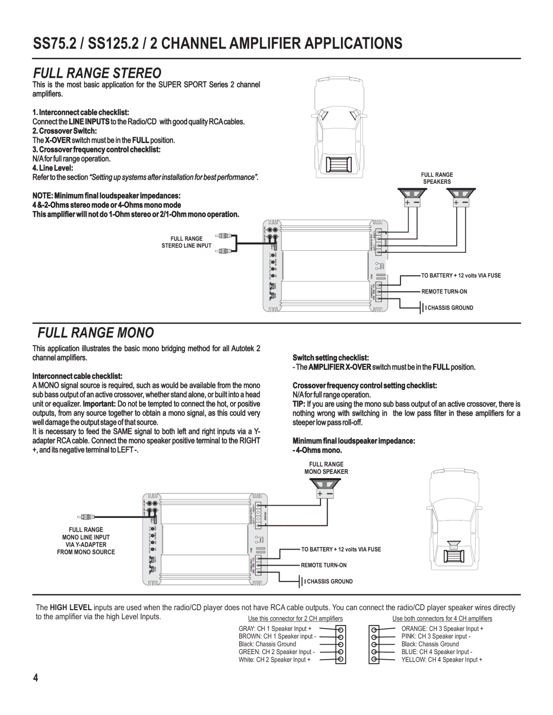
This is the most basic application for the SUPER SPORT Series 2 channel amplifiers.
1. Interconnect cable checklist:
Connect the LINE INPUTS to the Radio/CD with good quality RCA cables.
2. Crossover Switch:
The
3.Crossover frequency control checklist: N/A for full range operation.
4.Line Level:
Refer to the section “Setting up systems after installation for best performance”.
NOTE: Minimum final loudspeaker impedances:
4
This amplifier will not do
| LINE OUT | R |
| L |
FULL RANGE | LINE | R |
| L |
INPUT |
|
|
| |
STEREO LINE INPUT |
|
| I INPUT | - gnd - + |
|
| 5V 0.2V |
| LEVEL |
|
| 0dB 12dB |
| BASS EQ |
|
| 60Hz 1.2KHz |
| HPF |
|
| 30Hz 250Hz |
| LPF |
|
| FULL LPF HPF |
| |
|
| MONO STEREO |
| MODE |
|
|
|
|
| OUTPUT | |
|
|
|
|
| SPEAKER | LEFT + |
|
|
|
|
| FUSE | - |
|
|
|
|
| GND REM +12V | |
|
|
|
|
| POWER INPUT | |
|
|
|
|
| ||
|
|
|
|
|
|
|
|
|
|
|
|
|
|
|
|
|
|
|
|
|
RIDGE
| POWER | PROTECT |
|
|
|
|
|
|
|
|
|
|
|
|
|
|
|
|
|
|
|
|
|
|
|
|
|
|
|
|
|
|
FULL RANGE
SPEAKERS
TO BATTERY + 12 volts VIA FUSE
REMOTE
![]()
![]() CHASSIS GROUND
CHASSIS GROUND
FULL RANGE MONO
This application illustrates the basic mono bridging method for all Autotek 2 channel amplifiers.
Interconnect cable checklist:
A MONO signal source is required, such as would be available from the mono sub bass output of an active crossover, whether stand alone, or built into a head unit or equalizer. Important: Do not be tempted to connect the hot, or positive outputs, from any source together to obtain a mono signal, as this could very well damage the output stage of that source.
It is necessary to feed the SAME signal to both left and right inputs via a Y- adapter RCA cable. Connect the mono speaker positive terminal to the RIGHT +, and its negative terminal to LEFT
Switch setting checklist:
- The AMPLIFIER
Crossover frequency control setting checklist:
N/A for full range operation.
TIP: If you are using the mono sub bass output of an active crossover, there is nothing wrong with switching in the low pass filter in these amplifiers for a steeper low pass
Minimum final loudspeaker impedance: -
FULL RANGE
MONO SPEAKER
FULL RANGE
MONO LINE INPUT
VIA
FROM MONO SOURCE
LINE OUT | R | L |
LINE | R | L |
INPUT | I INPUT | - gnd - + |
| ||
| 5V 0.2V | LEVEL |
| 0dB 12dB | BASS EQ |
| 60Hz 1.2KHz | HPF |
| 30Hz 250Hz | LPF |
| FULL LPF HPF | |
| MONO STEREO | MODE |
|
|
|
|
| OUTPUT | |
|
|
|
|
| SPEAKER | LEFT + |
|
|
|
|
|
| - |
|
|
|
|
| FUSE | GND REM +12V |
|
|
|
|
| POWER INPUT | |
|
|
|
|
| ||
|
|
|
|
|
|
|
|
|
|
|
|
|
|
|
|
|
|
|
|
|
BRIDGED
| POWER | PROTECT |
|
|
|
|
|
|
|
|
|
|
|
|
|
|
|
|
|
|
|
|
|
|
|
|
|
|
|
|
|
|
TO BATTERY + 12 volts VIA FUSE
REMOTE
![]()
![]() CHASSIS GROUND
CHASSIS GROUND
The HIGH LEVEL inputs are used when the radio/CD player does not have RCA cable outputs. You can connect the radio/CD player speaker wires directly
to the amplifier via the high Level Inputs. | Use this connector for 2 CH amplifiers | Use both connectors for 4 CH amplifiers |
| GRAY: CH 1 Speaker Input + | ORANGE: CH 3 Speaker Input + |
| BROWN: CH 1 Speaker input - | PINK: CH 3 Speaker input - |
| Black: Chassis Ground | Black: Chassis Ground |
| GREEN: CH 2 Speaker Input - | BLUE: CH 4 Speaker Input - |
| White: CH 2 Speaker Input + | YELLOW: CH 4 Speaker Input + |
4