SEDIMENT TRAPS
Contaminants in the gas lines may cause improper operation of the gas control valve that may result in fire or explosion. Before attaching the gas line be sure that all gas pipe is clean on the inside. To trap any dirt or foreign material in the gas supply line, a drip leg (sometimes called a sediment trap) must be incorporated in the piping. The drip leg must be readily accessible. Install in accordance with the “Gas Piping” section. Refer to the current edition of the Natural Gas and Propane Installation Code CAN/CSA B149.1.
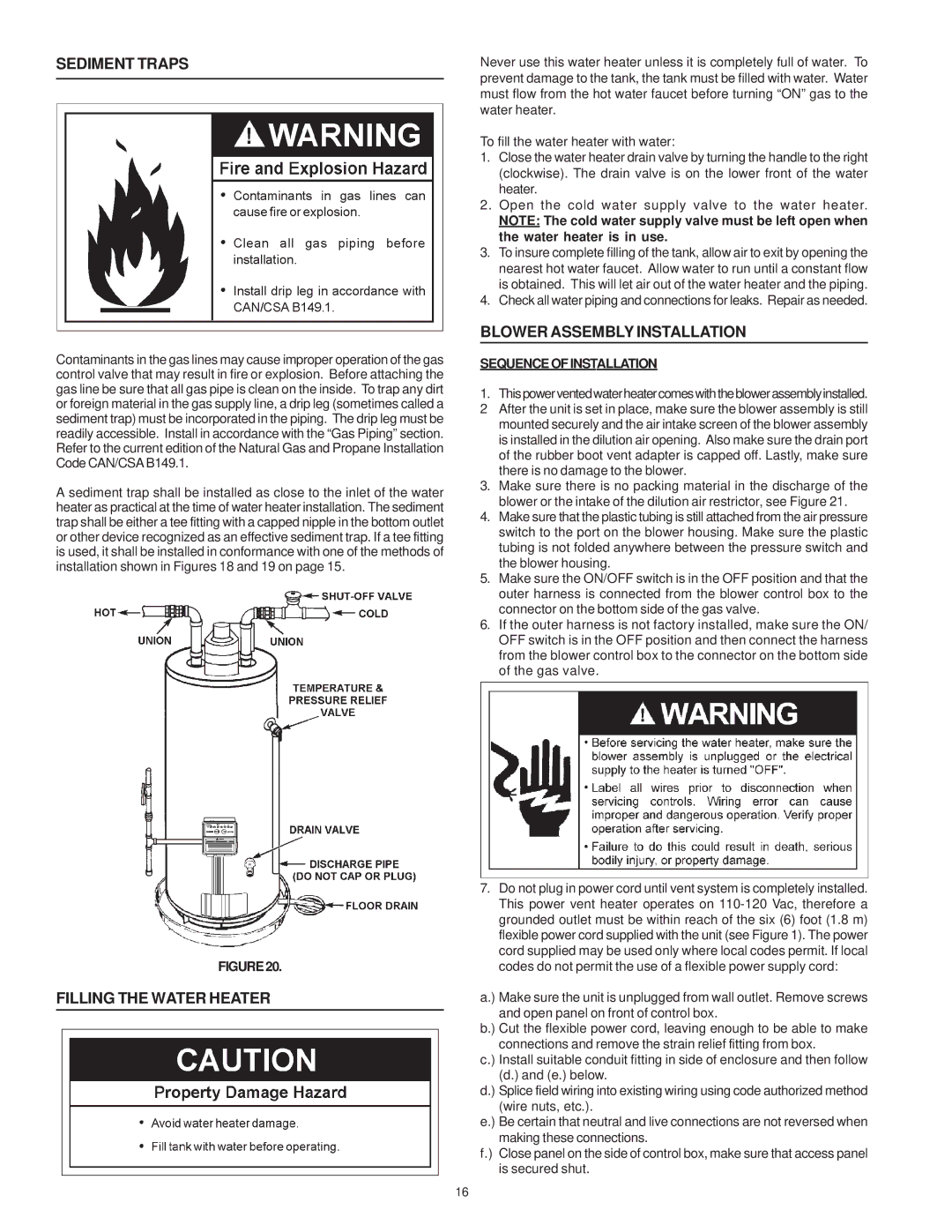
A sediment trap shall be installed as close to the inlet of the water heater as practical at the time of water heater installation. The sediment trap shall be either a tee fitting with a capped nipple in the bottom outlet or other device recognized as an effective sediment trap. If a tee fitting is used, it shall be installed in conformance with one of the methods of installation shown in Figures 18 and 19 on page 15.
FIGURE20.
FILLING THE WATER HEATER
Never use this water heater unless it is completely full of water. To prevent damage to the tank, the tank must be filled with water. Water must flow from the hot water faucet before turning “ON” gas to the water heater.
To fill the water heater with water:
1.Close the water heater drain valve by turning the handle to the right (clockwise). The drain valve is on the lower front of the water heater.
2.Open the cold water supply valve to the water heater.
NOTE: The cold water supply valve must be left open when the water heater is in use.
3.To insure complete filling of the tank, allow air to exit by opening the nearest hot water faucet. Allow water to run until a constant flow is obtained. This will let air out of the water heater and the piping.
4.Check all water piping and connections for leaks. Repair as needed.
BLOWER ASSEMBLY INSTALLATION
SEQUENCEOFINSTALLATION
1.Thispowerventedwaterheatercomeswiththeblowerassemblyinstalled.
2After the unit is set in place, make sure the blower assembly is still mounted securely and the air intake screen of the blower assembly is installed in the dilution air opening. Also make sure the drain port of the rubber boot vent adapter is capped off. Lastly, make sure there is no damage to the blower.
3.Make sure there is no packing material in the discharge of the blower or the intake of the dilution air restrictor, see Figure 21.
4.Make sure that the plastic tubing is still attached from the air pressure switch to the port on the blower housing. Make sure the plastic tubing is not folded anywhere between the pressure switch and the blower housing.
5.Make sure the ON/OFF switch is in the OFF position and that the outer harness is connected from the blower control box to the connector on the bottom side of the gas valve.
6.If the outer harness is not factory installed, make sure the ON/ OFF switch is in the OFF position and then connect the harness from the blower control box to the connector on the bottom side of the gas valve.
7.Do not plug in power cord until vent system is completely installed. This power vent heater operates on
a.) Make sure the unit is unplugged from wall outlet. Remove screws and open panel on front of control box.
b.) Cut the flexible power cord, leaving enough to be able to make connections and remove the strain relief fitting from box.
c.) Install suitable conduit fitting in side of enclosure and then follow (d.) and (e.) below.
d.) Splice field wiring into existing wiring using code authorized method (wire nuts, etc.).
e.) Be certain that neutral and live connections are not reversed when making these connections.
f.) Close panel on the side of control box, make sure that access panel is secured shut.
16