The input ratings shown on the data label are for elevations up to 2,000 feet (610 meters), unless elevation requirements of over 2,000 feet (610 meters) were specified at the time the dryer order was placed with the factory. The adjustment or conversion of dryers in the field for elevations over 2,000 feet (610 meters) is made by changing each burner orifice. If this conversion is necessary, contact the distributor who sold the dryer or contact the manufacturer.
IMPORTANT: If connection to this dryer is made with a flexible hose, it must be suitable for the appliance category in accordance with national installation regulations of the country of destination, and if in doubt the installer must contact the supplier. The manufacturer of this dryer does not recommend the use of flexible gas supply line/hose.
Pipe joint compounds that resist the action of natural, propane, and butane gases must be used.
In the U.S.A.: An individual manual shutoff valve must be installed within 6 feet (1.8 meters) of the dryer in accordance with the National Fuel Gas Code, ANSI Z223.1.
In Canada: An individual manual shutoff valve must be installed in accordance with the B149.1, Natural Gas and Propane Installation Code. It is recommended that an individual manual shutoff valve be installed within 6 feet (1.8 meters) of the dryer.
Natural Gas Specifications**
Nominal | Supply | Gross |
| Orifice | Orifice | Burner | ||
Heating |
| |||||||
Value | Pressure | Heat Input | Size* | (Injector) | Pressure | |||
|
|
|
|
|
|
| Quantity |
|
B tu/ft3 | in wc | Btu/hr |
| kW | DMS | mm | in wc | |
|
| |||||||
|
|
|
|
|
|
|
|
|
1,000 | 224,000 |
| 65.64 | 5 | 5.2197 | 2 | 3.5 | |
*Consult factory for elevations over 2,000 feet (609.6 meters) for correct burner orifice size(s).
**Btu rating for both tumblers.
Gas Connections
Inlet | connection | 3/4” M.N.P.T. |
Inlet | supply size .... | 3/4” Pipe (minimum) |
Piping/Connections
The dryer is provided with a 3/4” N.P.T. inlet pipe connection on top of the dryer. It is recommended that a gas shutoff valve be provided to the gas supply line of each dryer for ease in servicing.
The size of the main gas supply line (header) will vary depending on the distance this line travels from the gas meter. Specific information regarding supply line size should be determined by the gas supplier.
NOTE: Undersized gas supply piping can create a low or inconsistent pressure, which will result in erratic operation of the burner ignition system.
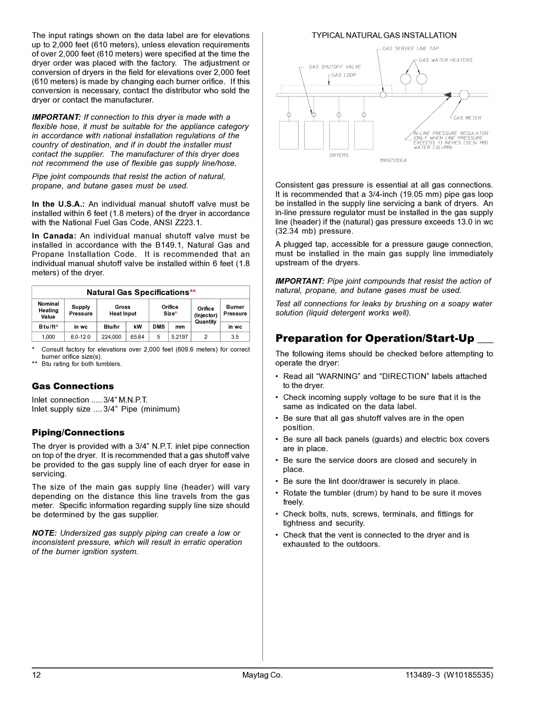
TYPICAL NATURAL GAS INSTALLATION
Consistent gas pressure is essential at all gas connections. It is recommended that a
A plugged tap, accessible for a pressure gauge connection, must be installed in the main gas supply line immediately upstream of the dryers.
IMPORTANT: Pipe joint compounds that resist the action of natural, propane, and butane gases must be used.
Test all connections for leaks by brushing on a soapy water solution (liquid detergent works well).
Preparation for Operation/Start-Up ___
The following items should be checked before attempting to operate the dryer:
•Read all “WARNING” and “DIRECTION” labels attached to the dryer.
•Check incoming supply voltage to be sure that it is the same as indicated on the data label.
•Be sure that all gas shutoff valves are in the open position.
•Be sure all back panels (guards) and electric box covers are in place.
•Be sure the service doors are closed and securely in place.
•Be sure the lint door/drawer is securely in place.
•Rotate the tumbler (drum) by hand to be sure it moves freely.
•Check bolts, nuts, screws, terminals, and fittings for tightness and security.
•Check that the vent is connected to the dryer and is exhausted to the outdoors.
12 | Maytag Co. | 113489 - 3 (W10185535) |