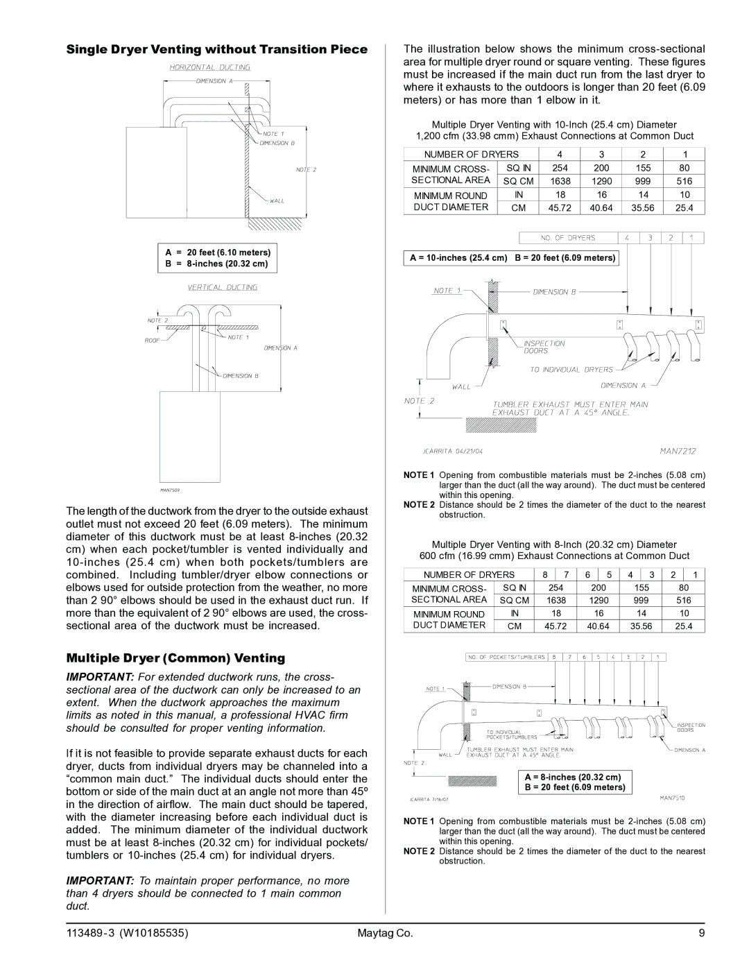
Single Dryer Venting without Transition Piece
A= 20 feet (6.10 meters)
B=
The length of the ductwork from the dryer to the outside exhaust outlet must not exceed 20 feet (6.09 meters). The minimum diameter of this ductwork must be at least
Multiple Dryer (Common) Venting
IMPORTANT: For extended ductwork runs, the cross- sectional area of the ductwork can only be increased to an extent. When the ductwork approaches the maximum limits as noted in this manual, a professional HVAC firm should be consulted for proper venting information.
If it is not feasible to provide separate exhaust ducts for each dryer, ducts from individual dryers may be channeled into a “common main duct.” The individual ducts should enter the bottom or side of the main duct at an angle not more than 45º in the direction of airflow. The main duct should be tapered, with the diameter increasing before each individual duct is added. The minimum diameter of the individual ductwork must be at least
IMPORTANT: To maintain proper performance, no more than 4 dryers should be connected to 1 main common duct.
The illustration below shows the minimum
Multiple Dryer Venting with
1,200 cfm (33.98 cmm) Exhaust Connections at Common Duct
NUMBER OF DRYERS | 4 | 3 | 2 | 1 | |
MINIMUM CROSS- | SQ IN | 254 | 200 | 155 | 80 |
SECTIONAL AREA | SQ CM | 1638 | 1290 | 999 | 516 |
MINIMUM ROUND | IN | 18 | 16 | 14 | 10 |
DUCT DIAMETER | CM | 45.72 | 40.64 | 35.56 | 25.4 |
A =
NOTE 1 Opening from combustible materials must be
NOTE 2 Distance should be 2 times the diameter of the duct to the nearest obstruction.
Multiple Dryer Venting with
600 cfm (16.99 cmm) Exhaust Connections at Common Duct
NUMBER OF DRYERS | 8 | 7 |
| 6 | 5 |
|
| 4 | 3 |
| 2 | 1 | ||||||||||
MINIMUM CROSS- | SQ IN | 254 |
|
| 200 |
|
|
| 155 |
| 80 | |||||||||||
SECTIONAL AREA | SQ CM | 1638 |
| 1290 |
|
| 999 |
| 516 | |||||||||||||
MINIMUM ROUND | IN | 18 |
|
| 16 |
|
|
| 14 |
| 10 | |||||||||||
DUCT DIAMETER | CM | 45.72 |
| 40.64 |
|
| 35.56 |
| 25.4 | |||||||||||||
|
|
|
|
|
|
|
|
|
|
|
|
|
|
|
|
|
|
|
|
|
|
|
|
|
|
|
|
|
|
|
|
|
|
|
|
|
|
|
|
|
|
|
|
|
|
|
|
|
|
|
|
|
|
|
|
|
|
|
|
|
|
|
|
|
|
|
|
|
|
|
|
|
|
|
|
|
|
|
|
|
|
|
|
|
|
|
|
|
|
|
|
|
|
|
|
|
|
|
|
|
|
|
|
|
|
|
|
|
|
|
|
|
|
|
|
|
|
|
|
|
|
|
|
|
|
|
|
|
|
|
|
|
|
|
|
|
|
|
|
|
|
|
|
|
|
|
|
|
|
|
|
|
|
|
|
|
|
|
|
|
A =
B = 20 feet (6.09 meters)
NOTE 1 Opening from combustible materials must be
NOTE 2 Distance should be 2 times the diameter of the duct to the nearest obstruction.
113489 - 3 (W10185535) | Maytag Co. | 9 |
