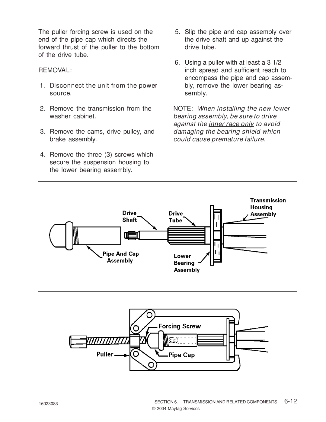
The puller forcing screw is used on the end of the pipe cap which directs the forward thrust of the puller to the bottom of the drive tube.
REMOVAL:
1.Disconnect the unit from the power source.
2.Remove the transmission from the washer cabinet.
3.Remove the cams, drive pulley, and brake assembly.
4.Remove the three (3) screws which secure the suspension housing to the lower bearing assembly.
5.Slip the pipe and cap assembly over the drive shaft and up against the drive tube.
6.Using a puller with at least a 3 1/2 inch spread and sufficient reach to encompass the pipe and cap assem- bly, remove the lower bearing as- sembly.
NOTE: When installing the new lower bearing assembly, be sure to drive against the inner race only to avoid damaging the bearing shield which could cause premature failure.
16023083 | SECTION 6. TRANSMISSION AND RELATED COMPONENTS |
| © 2004 Maytag Services |