Component Testing Procedures
!WARNING
To avoid risk of electrical shock, personal injury or death; disconnect power and shut off gas to unit before servicing, unless testing requires power.
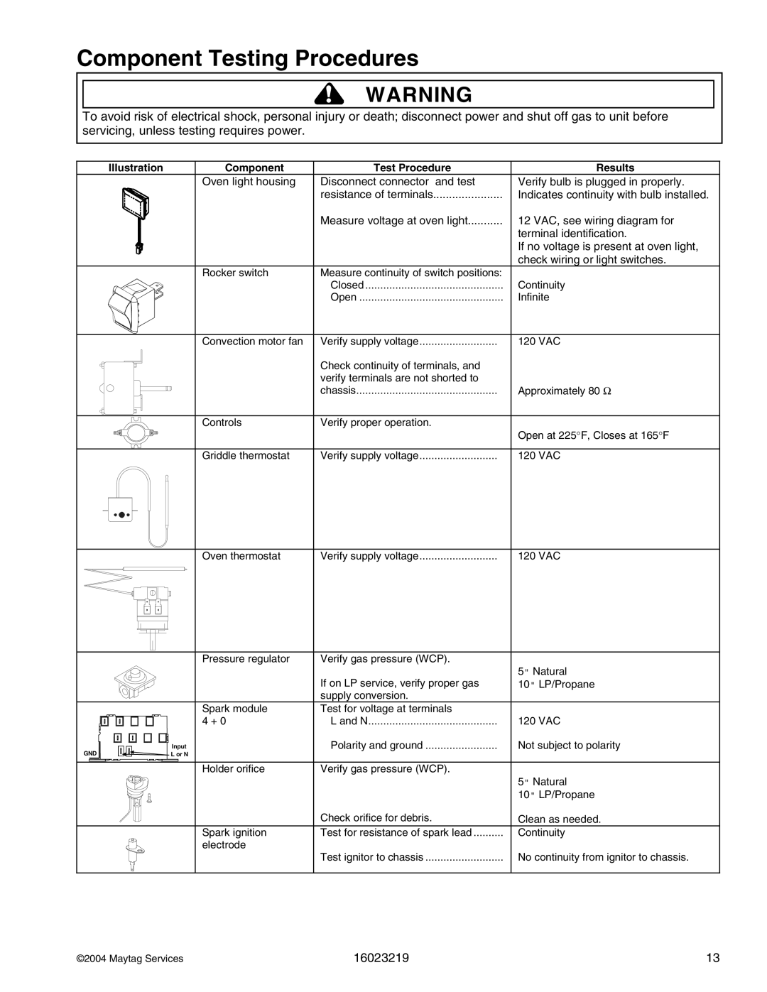
Illustration | Component | Test Procedure | Results |
| Oven light housing | Disconnect connector and test | Verify bulb is plugged in properly. |
|
| resistance of terminals | Indicates continuity with bulb installed. |
|
| Measure voltage at oven light | 12 VAC, see wiring diagram for |
|
|
| terminal identification. |
|
|
| If no voltage is present at oven light, |
|
|
| check wiring or light switches. |
| Rocker switch | Measure continuity of switch positions: |
|
|
| Closed | Continuity |
|
| Open | Infinite |
| Convection motor fan | Verify supply voltage | 120 VAC |
|
| Check continuity of terminals, and |
|
|
| verify terminals are not shorted to | Approximately 80 Ω |
|
| chassis | |
| Controls | Verify proper operation. | Open at 225°F, Closes at 165°F |
|
|
| |
| Griddle thermostat | Verify supply voltage | 120 VAC |
Oven thermostat | Verify supply voltage | 120 VAC |
| Pressure regulator | Verify gas pressure (WCP). |
|
|
| If on LP service, verify proper gas | 5" Natural |
|
| 10" LP/Propane | |
|
| supply conversion. |
|
| Spark module | Test for voltage at terminals |
|
| 4 + 0 | L and N | 120 VAC |
GND | Input | Polarity and ground | Not subject to polarity |
L or N |
|
| |
| Holder orifice | Verify gas pressure (WCP). |
|
|
|
| 5" Natural |
|
|
| 10" LP/Propane |
|
| Check orifice for debris. | Clean as needed. |
| Spark ignition | Test for resistance of spark lead | Continuity |
| electrode |
|
|
|
| Test ignitor to chassis | No continuity from ignitor to chassis. |
©2004 Maytag Services | 16023219 | 13 |