Component Testing Procedures
!WARNING
To avoid risk of electrical shock, personal injury or death; disconnect power and shut off gas to unit before servicing, unless testing requires power.
Illustration | Component | Test Procedure | Results |
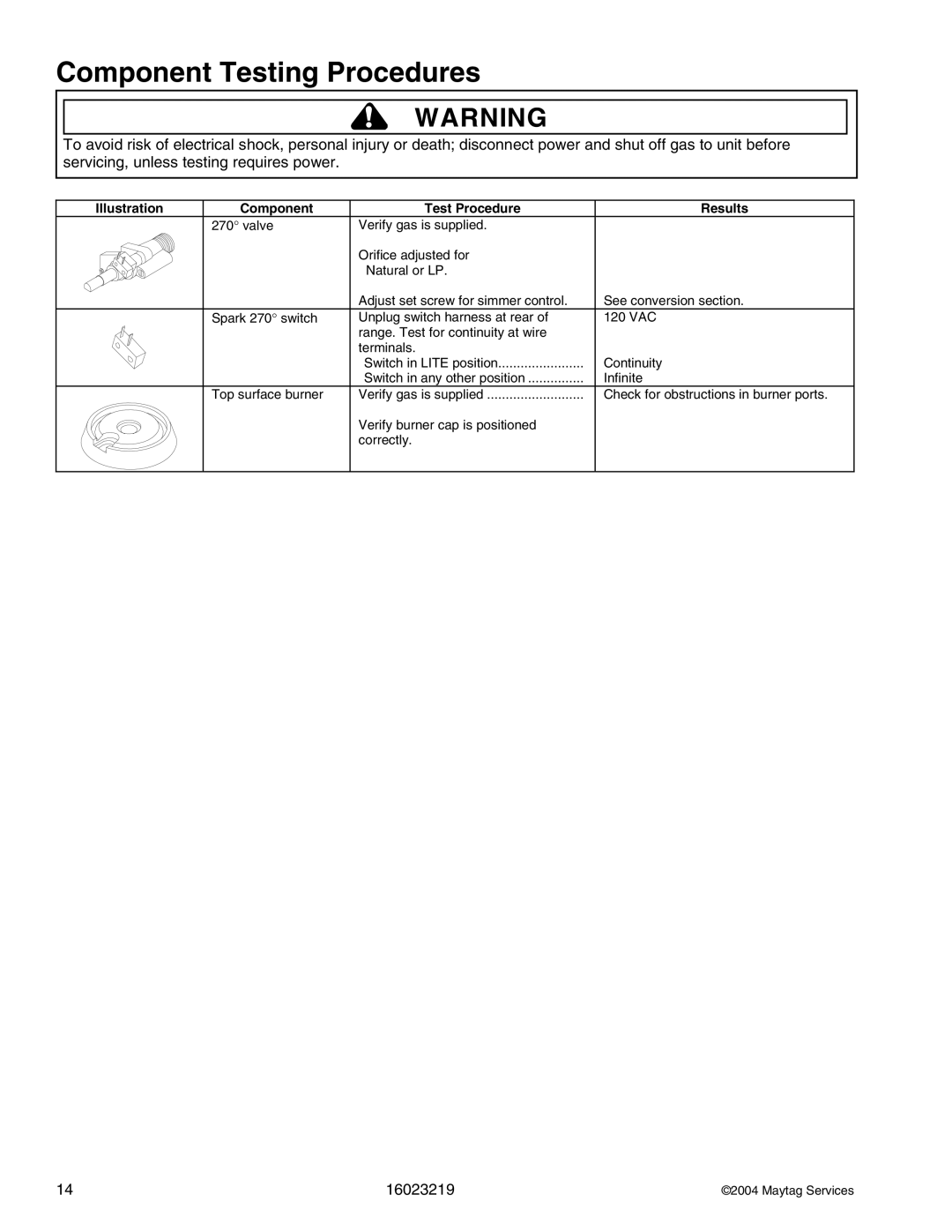
| 270° valve | Verify gas is supplied. |
|
|
| Orifice adjusted for |
|
|
| Natural or LP. |
|
|
| Adjust set screw for simmer control. | See conversion section. |
| Spark 270° switch | Unplug switch harness at rear of | 120 VAC |
|
| range. Test for continuity at wire |
|
|
| terminals. |
|
|
| Switch in LITE position | Continuity |
|
| Switch in any other position | Infinite |
| Top surface burner | Verify gas is supplied | Check for obstructions in burner ports. |
Verify burner cap is positioned correctly.
14 | 16023219 | ©2004 Maytag Services |