Manuals
/
Maytag
/
Kitchen Appliance
/
Range
Maytag
W10252706B Direct Wire Installation Copper or Aluminum Wire, wire Connection Direct Wire
Models:
W10252706B
1
10
16
16
Download
16 pages
15.21 Kb
7
8
9
10
11
12
13
14
Install
Direct Wire
Dimension
Safety
Page 10
Image 10
Page 9
Page 11
Page 10
Image 10
Page 9
Page 11
Contents
INSTALLATION INSTRUCTIONS 30 76 CM FREESTANDING ELECTRIC RANGES
W10252706B
Table of Contents
Your safety and the safety of others are very important
RANGE SAFETY
DANGER
Tools and Parts
INSTALLATION REQUIREMENTS
Mobile Home - Additional Installation Requirements
Location Requirements
Electrical Requirements - U.S.A. Only
Product Dimensions
Cabinet Dimensions
A C B D E
If connecting to a 3-wire system
If connecting to a 4-wire system
Electrical Connection
Unpack Range
INSTALLATION INSTRUCTIONS
Install Anti-Tip Bracket
A D C B
Direct Wire
Power Supply Cord
Electrical Connection - U.S.A. Only
Style 2 Direct wire strain relief
4-wire connection Power Supply Cord
Style 1 Power supply cord strain relief
connecting to
E. Neutral center wire
3-wire connection Power Supply Cord
A B C D
D. Neutral white wire
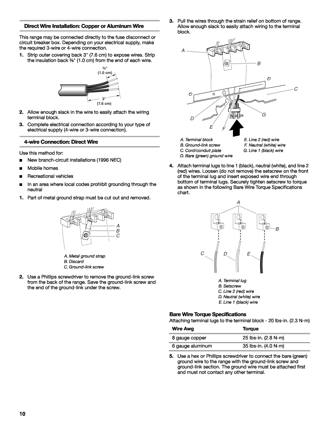
Bare Wire Torque Specifications
Direct Wire Installation Copper or Aluminum Wire
4-wire Connection Direct Wire
A B CDE
D. Bare green ground wire
3-wire connection Direct Wire
A B CD E
E. Neutral white wire
Storage Drawer
Verify Anti-Tip Bracket Location
Level Range
To Remove
Complete Installation
To Replace
For direct-wired ranges
For power supply cord-connected ranges
Moving the Range
ANTI-TIP BRACKET TEMPLATE
Top edge Left edge
9/09
W10252706B
2009
All rights reserved
Top
Page
Image
Contents