Upper Shaft
Coupler
![]() WARNING: Always wear eye protec- tion and hearing protection. Never lean over
WARNING: Always wear eye protec- tion and hearing protection. Never lean over
Lower
LOOSEN
the trimmer head. Rocks or debris can rico- chet or be thrown into eyes and face and
Attachment
TIGHTEN Knob
2.Press and hold the locking/release button. Locking/Release
Button
Coupler | Upper Shaft | |
Lower Attachment | ||
|
3.While securely holding the engine and up- per shaft, pull the attachment straight out of the coupler.
INSTALLING OPTIONAL ATTACH- MENTS
1.Remove the shaft cap from the attach- ment (if present).
2.Position locking/release button of attach- ment into guide recess of coupler.
3.Push the attachment into the coupler until the locking/release button snaps into the primary hole.
4.Before using the unit, tighten the knob se- curely by turning clockwise.
Coupler | Primary Hole |
| Guide Recess |
Upper | Locking/ Attachment |
Shaft | Release |
| Button |
![]() WARNING: Make sure the locking/ release button is locked in the primary hole and the knob is securely tightened before op- erating the unit.
WARNING: Make sure the locking/ release button is locked in the primary hole and the knob is securely tightened before op- erating the unit.
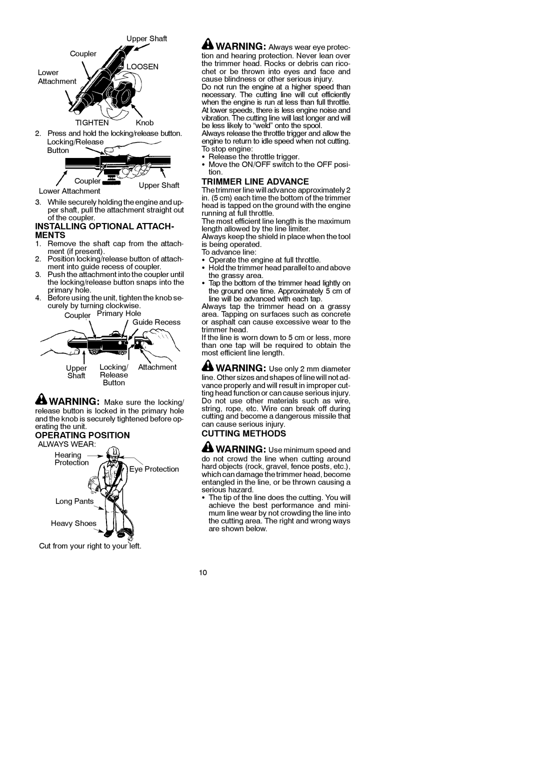
OPERATING POSITION
cause blindness or other serious injury.
Do not run the engine at a higher speed than necessary. The cutting line will cut efficiently when the engine is run at less than full throttle. At lower speeds, there is less engine noise and vibration. The cutting line will last longer and will be less likely to “weld” onto the spool.
Always release the throttle trigger and allow the engine to return to idle speed when not cutting. To stop engine:
SRelease the throttle trigger.
SMove the ON/OFF switch to the OFF posi- tion.
TRIMMER LINE ADVANCE
The trimmer line will advance approximately 2 in. (5 cm) each time the bottom of the trimmer head is tapped on the ground with the engine running at full throttle.
The most efficient line length is the maximum length allowed by the line limiter.
Always keep the shield in place when the tool is being operated.
To advance line:
SOperate the engine at full throttle.
SHold the trimmer head parallel to and above
the grassy area.
STap the bottom of the trimmer head lightly on the ground one time. Approximately 5 cm of
line will be advanced with each tap. Always tap the trimmer head on a grassy area. Tapping on surfaces such as concrete or asphalt can cause excessive wear to the trimmer head.
If the line is worn down to 5 cm or less, more than one tap will be required to obtain the most efficient line length.
![]() WARNING: Use only 2 mm diameter line. Other sizes and shapes of line will not ad- vance properly and will result in improper cut- ting head function or can cause serious injury. Do not use other materials such as wire, string, rope, etc. Wire can break off during cutting and become a dangerous missile that can cause serious injury.
WARNING: Use only 2 mm diameter line. Other sizes and shapes of line will not ad- vance properly and will result in improper cut- ting head function or can cause serious injury. Do not use other materials such as wire, string, rope, etc. Wire can break off during cutting and become a dangerous missile that can cause serious injury.
CUTTING METHODS
ALWAYS WEAR:
Hearing
Protection
Long Pants
Heavy Shoes
Eye Protection
![]() WARNING: Use minimum speed and do not crowd the line when cutting around hard objects (rock, gravel, fence posts, etc.), which can damage the trimmer head, become entangled in the line, or be thrown causing a serious hazard.
WARNING: Use minimum speed and do not crowd the line when cutting around hard objects (rock, gravel, fence posts, etc.), which can damage the trimmer head, become entangled in the line, or be thrown causing a serious hazard.
SThe tip of the line does the cutting. You will achieve the best performance and mini- mum line wear by not crowding the line into the cutting area. The right and wrong ways are shown below.
Cut from your right to your left.
10