33ZCSECTRM, 33ZCVAVTRM, 33ZCFANTRM specifications
The Carrier 33ZCFANTRM, 33ZCSECTRM, and 33ZCVAVTRM are advanced air conditioning units designed for commercial and light industrial applications. These models represent Carrier's commitment to innovation and energy efficiency, offering unbeatable performance while ensuring minimal environmental impact.One of the main features of the Carrier 33ZCFANTRM series is its outstanding energy efficiency. These units are designed to meet or exceed Energy Efficiency Ratio (EER) standards, which translates to reduced energy consumption and lower utility bills for users. The implementation of variable speed drive technology allows for precise control of airflow and cooling, enabling the units to adapt to varying load requirements seamlessly. This not only enhances comfort levels but also optimizes energy use.
In terms of design, the Carrier 33ZCSECTRM model stands out with its compact footprint, making it ideal for installation in tight spaces. It features a robust chassis made from high-quality materials that ensure durability and resistance to harsh outdoor conditions. Additionally, the unit is equipped with sound-dampening technology, resulting in quieter operation compared to many traditional systems.
The 33ZCVAVTRM model takes versatility to the next level by incorporating advanced Variable Air Volume (VAV) technology. This allows for customized airflow delivery, ensuring that different areas of a building can be conditioned to meet specific comfort needs. The VAV system helps maintain optimal indoor air quality by continuously monitoring and adjusting airflows based on real-time demand.
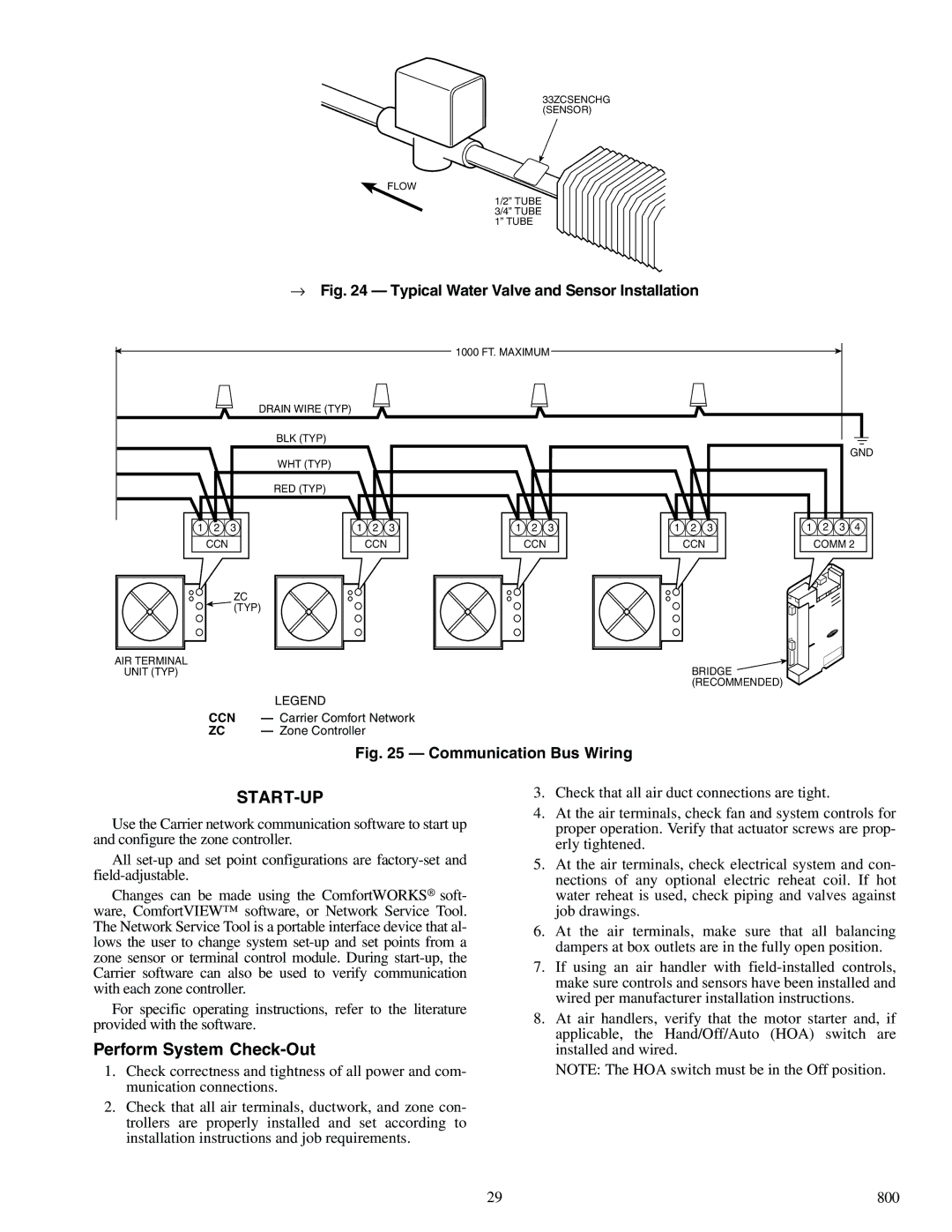
Each model also features advanced controls which integrate seamlessly with building management systems. This connectivity provides users with powerful tools for monitoring system performance, enabling predictive maintenance and improving overall operational efficiency.
Moreover, the Carrier 33ZC series employs environmentally friendly refrigerants, which aligns with global sustainability goals. The use of these refrigerants contributes to a lower carbon footprint while still delivering exceptional cooling capacity.
Overall, the Carrier 33ZCFANTRM, 33ZCSECTRM, and 33ZCVAVTRM models epitomize Carrier's innovative spirit, combining cutting-edge technology with superior performance features. These units are well-suited to meet the rigorous demands of diverse commercial applications, promoting both comfort and efficiency in today's dynamic work environments. As businesses evolve, the need for reliable, efficient, and adaptable HVAC solutions becomes paramount, and these Carrier models stand ready to meet that challenge head-on.

