2
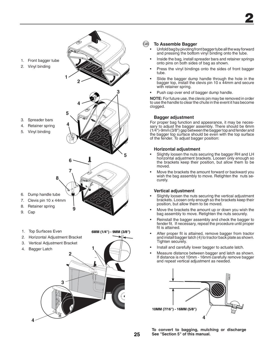
1. Front bagger tube
2. Vinyl binding
1
2
4
|
| 5 |
3. | Spreader bars | 4 |
4. | Retainer spring | |
5. | Vinyl binding |
|
6
7
8
6. Dump handle tube
7. Clevis pin 10 x 44mm
02905
3
906 02
5
To Assemble Bagger
•Unfold bag by pivoting front bagger tube all the way forward and pressing the bottom vinyl binding onto the tube.
•Inside the bag, install spreader bars and retainer springs onto pins on both sides of bag as shown.
•Press the vinyl bindings onto the sides of front bagger tube.
•Slide the bagger dump handle through the hole in the bagger top, install the clevis pin 10 x 44mm and secure with retainer spring.
•Push cap over end of bagger dump handle.
NOTE: For future use, the clevis pin may be removed in order to use the handle to clear the chute in the event it has become clogged.
Bagger adjustment
For proper bag function and appearance, it may be neces- sary to adjust the bagger assembly. There should be 6mm
Horizontal adjustment
•Slightly loosen the nuts securing the bagger RH and LH horizontal adjustment brackets. Loosen only enough so the brackets keep their position, but allow them to be moved.
•Move the brackets the amount forward or backward you wish the bag assembly to move. Retighten the nuts se- curely.
Vertical adjustment
• Slightly loosen the nuts securing the vertical adjustment |
brackets. Loosen only enough so the brackets keep their |
position, but allow them to be moved. |
8. Retainer spring
9. Cap
9
02907
• | Move the brackets the amount up or down you wish the |
| bag assembly to move. Retighten the nuts securely. |
• | Reinstall the bagger assembly and check the bagger to |
| fender fit. If necessary, repeat the procedure until proper |
| fit is attained. |
1. | Top Surfaces Even | 6MM (1/4") - 9MM (3/8") |
2. | Horizontal Adjustment Bracket |
|
3. | Vertical Adjustment Bracket | 1 |
4. | Bagger Latch |
2
3
02967 ![]()
4 ![]()
• After proper fit is attained, remove bagger from tractor |
and install bagger latch (4) to tractor back plate as shown. |
Tighten securely. |
• Install and carefully lower bagger to actuate latch. |
• Measure distance between bagger and latch as shown. |
If distance is not 10mm - 16mm carefully remove bagger |
and repeat vertical adjustment as needed. |
02983
10MM (7/16") - 16MM (5/8")
4
To convert to bagging, mulching or discharge
25See "Section 5" of this manual.