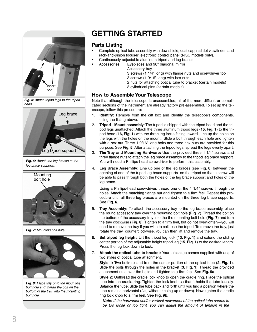
Insert bolt
Fig. 5: Attach tripod legs to the tripod head.
Leg brace
Leg brace support
Fig. 6: Attach the leg braces to the
leg brace supports.
Mounting bolt hole
Fig. 7: Mounting bolt hole.
Fig. 8: Place tray onto the mounting bolt hole and thread the bolt on the bottom of the tray into the mounting bolt hole.
GETTING STARTED
Parts Listing
•Complete optical tube assembly with dew shield, dust cap, red dot viewfinder, and
•Continuously adjustable aluminum tripod and leg braces.
•Accessories: Eyepieces and 90° diagonal mirror
Accessory tray
3 screws (1 1/4" long) with flange nuts and screwdriver tool 3 screws (1 9/16" long) with hex nuts
2 nuts for attaching optical tube to bracket (certain models) 3 cylindrical pins (certain models)
How to Assemble Your Telescope
Note that although the telescope is unassembled, all of the more difficult or compli- cated sections of the instrument are already factory
1.Identify: Remove from the gift box and identify the telescope’s components, using the listing above.
2.Tripod - Mount assembly: The tripod is shipped with the tripod head and the tri- pod legs unattached. Attach the three aluminum tripod legs (15, Fig. 1) to the tri- pod head (16, Fig. 1) with the three leg locks facing inward. Line up the holes on the legs with the holes on the mount. Slide a bolt through each hole and tighten with a hex nut. Three 1 9/16" long bolts and three hex nuts are provided for this purpose. See Fig. 5. After attaching the tripod legs, spread the legs evenly apart.
3.The Tray and Mounting Hardware: Use the provided three 1 1/4" screws and three flange nuts to attach the leg brace assembly to the tripod leg brace support. You will need a
4.Leg Brace Assembly: Line up one of the leg braces (see Fig. 6) between the opening of one of the tripod leg brace supports on the tripod so that a screw will be able to pass through both the holes of the leg brace support and holes of the leg brace.
Using a
5.Tray Assembly: To attach the accessory tray to the leg brace assembly, place the round accessory tray over the mounting bolt hole (Fig. 7). Thread the bolt on the bottom of the accessory tray into the the mounting bolt hole (Fig. 7) and turn the tray clockwise (Fig. 8). Tighten to a firm feel, but do not
6.Set tripod leg height: Lift the tripod leg lock (13, Fig. 1) and extend the sliding center portion of the adjustable height tripod leg (15, Fig. 1) to the desired length. Press the leg lock down to lock.
7.Attach the optical tube to bracket: Your telescope comes supplied with one of two styles of optical tube attachment.
Style 1: Two bolts extend from the center portion of the optical tube (2, Fig. 1). Slide the bolts through the holes in the bracket (3, Fig. 1). Thread the provided attachment nuts over the bolts and tighten to a firm feel. See Fig. 9a.
Style 2: Unthread the cradle lock knob to open the cradle ring. Place the optical tube into the cradle ring. Tighten the lock knob so that it holds the tube loosely. Balance the tube: Slide the tube back and forth until you find a position where the tube remains horizontal (i.e., without tipping up or down). Now tighten the cradle ring lock knob to a firm feel. See Fig. 9b.
Note: If the horizontal and/or vertical movement of the optical tube seems to be too loose or too tight, you can adjust the amount of tension in the
8