Specifications |
Counter
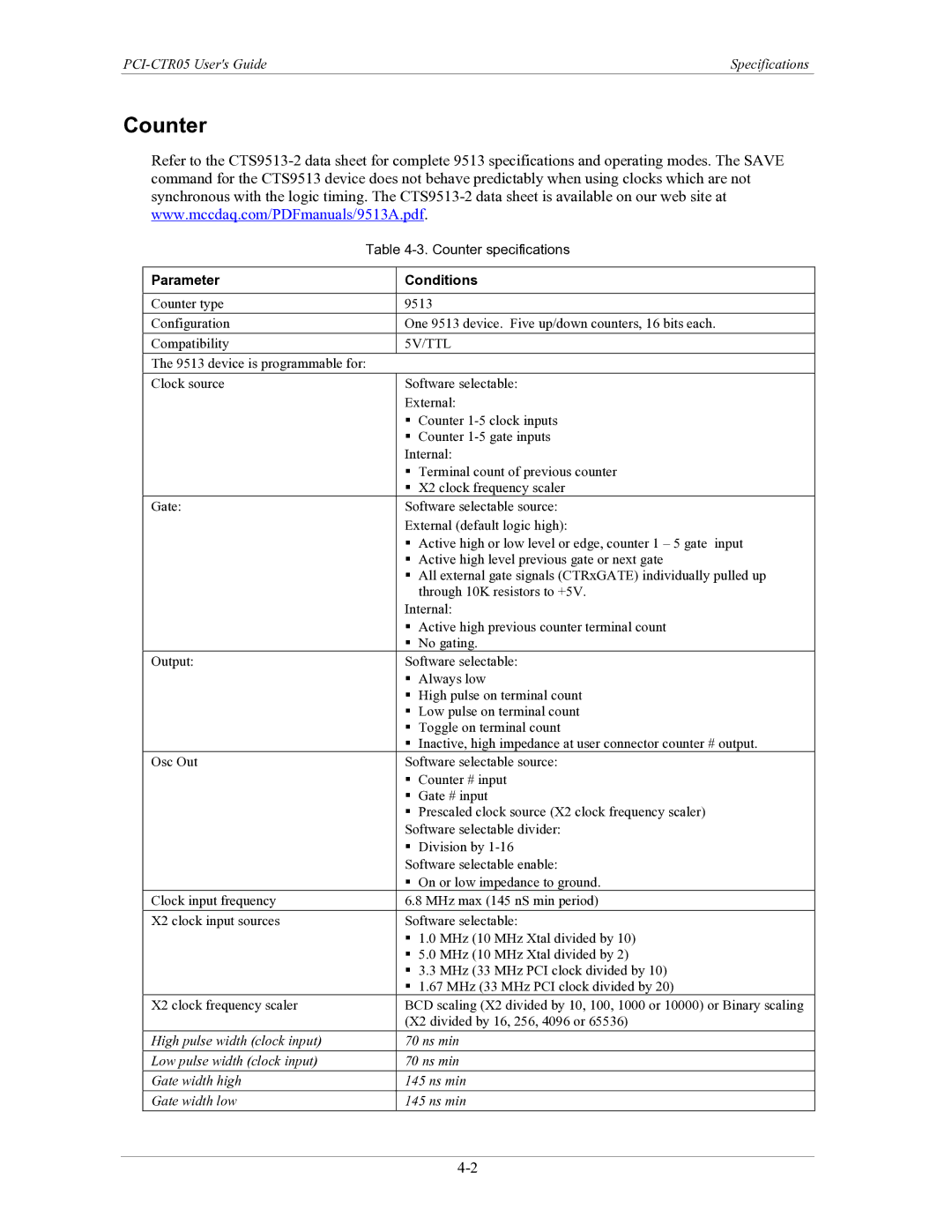
Refer to the
| Table | ||
|
|
| |
Parameter |
| Conditions | |
|
|
| |
Counter type |
| 9513 | |
Configuration |
| One 9513 device. Five up/down counters, 16 bits each. | |
Compatibility |
| 5V/TTL | |
The 9513 device is programmable for: |
| ||
Clock source |
| Software selectable: | |
|
| External: | |
|
| | Counter |
|
| | Counter |
|
| Internal: | |
|
| | Terminal count of previous counter |
|
| | X2 clock frequency scaler |
Gate: |
| Software selectable source: | |
|
| External (default logic high): | |
|
| | Active high or low level or edge, counter 1 – 5 gate input |
|
| | Active high level previous gate or next gate |
|
| | All external gate signals (CTRxGATE) individually pulled up |
|
|
| through 10K resistors to +5V. |
|
| Internal: | |
|
| | Active high previous counter terminal count |
|
| | No gating. |
Output: |
| Software selectable: | |
|
| | Always low |
|
| | High pulse on terminal count |
|
| | Low pulse on terminal count |
|
| | Toggle on terminal count |
|
| | Inactive, high impedance at user connector counter # output. |
Osc Out |
| Software selectable source: | |
|
| | Counter # input |
|
| | Gate # input |
|
| | Prescaled clock source (X2 clock frequency scaler) |
|
| Software selectable divider: | |
|
| | Division by |
|
| Software selectable enable: | |
|
| | On or low impedance to ground. |
Clock input frequency |
| 6.8 MHz max (145 nS min period) | |
X2 clock input sources |
| Software selectable: | |
|
| | 1.0 MHz (10 MHz Xtal divided by 10) |
|
| | 5.0 MHz (10 MHz Xtal divided by 2) |
|
| | 3.3 MHz (33 MHz PCI clock divided by 10) |
|
| | 1.67 MHz (33 MHz PCI clock divided by 20) |
X2 clock frequency scaler |
| BCD scaling (X2 divided by 10, 100, 1000 or 10000) or Binary scaling | |
|
| (X2 divided by 16, 256, 4096 or 65536) | |
High pulse width (clock input) |
| 70 ns min | |
Low pulse width (clock input) |
| 70 ns min | |
Gate width high |
| 145 ns min | |
Gate width low |
| 145 ns min | |