Specifications |
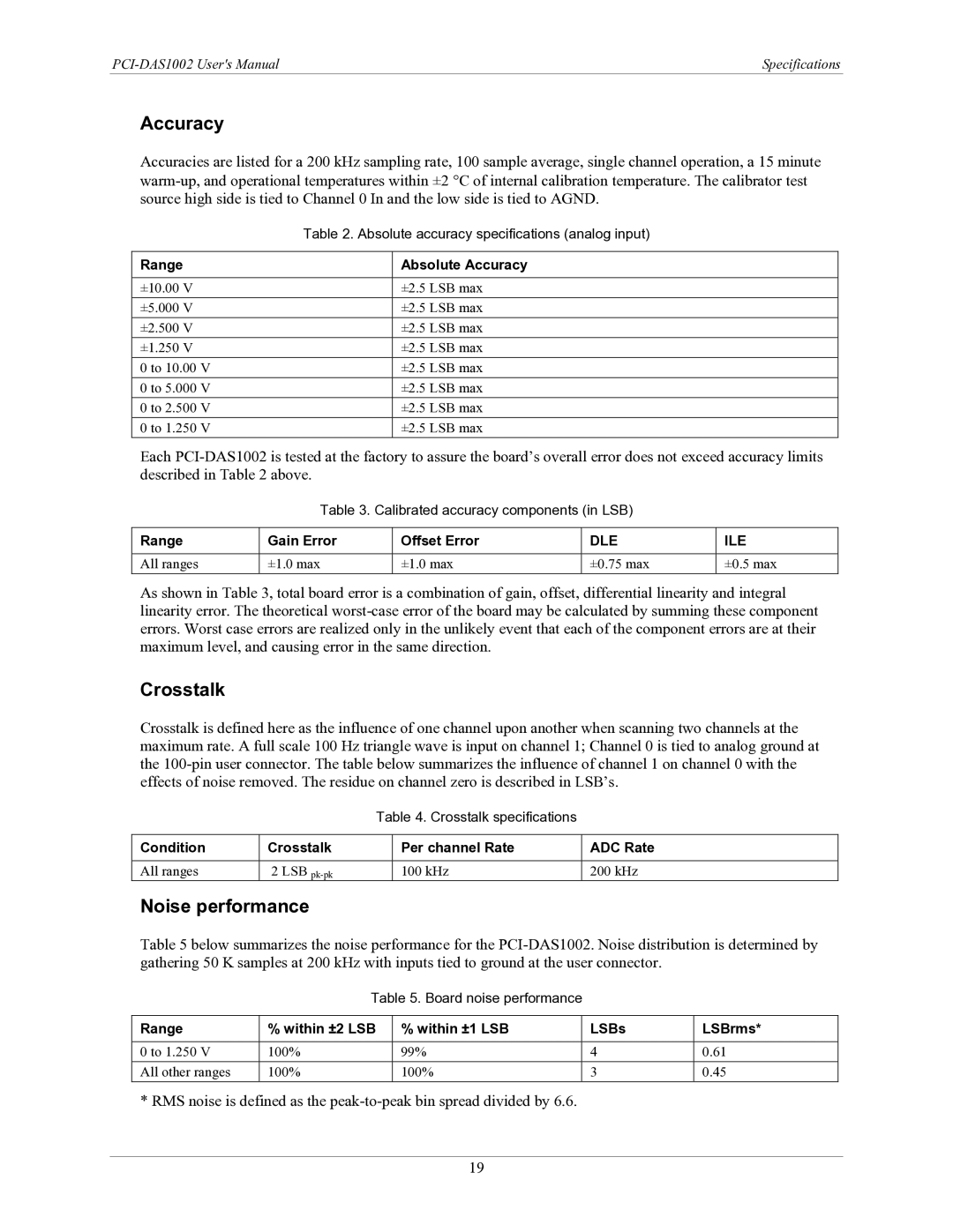
Accuracy
Accuracies are listed for a 200 kHz sampling rate, 100 sample average, single channel operation, a 15 minute
| Table 2. Absolute accuracy specifications (analog input) | |
|
|
|
Range |
| Absolute Accuracy |
|
|
|
±10.00 V |
| ±2.5 LSB max |
±5.000 V |
| ±2.5 LSB max |
±2.500 V |
| ±2.5 LSB max |
±1.250 V |
| ±2.5 LSB max |
0 to 10.00 V |
| ±2.5 LSB max |
0 to 5.000 V |
| ±2.5 LSB max |
0 to 2.500 V |
| ±2.5 LSB max |
0 to 1.250 V |
| ±2.5 LSB max |
Each
Table 3. Calibrated accuracy components (in LSB)
Range | Gain Error | Offset Error | DLE | ILE |
|
|
|
|
|
All ranges | ±1.0 max | ±1.0 max | ±0.75 max | ±0.5 max |
As shown in Table 3, total board error is a combination of gain, offset, differential linearity and integral linearity error. The theoretical
Crosstalk
Crosstalk is defined here as the influence of one channel upon another when scanning two channels at the maximum rate. A full scale 100 Hz triangle wave is input on channel 1; Channel 0 is tied to analog ground at the
Table 4. Crosstalk specifications
Condition | Crosstalk | Per channel Rate | ADC Rate |
|
|
|
|
All ranges | 2 LSB | 100 kHz | 200 kHz |
Noise performance
Table 5 below summarizes the noise performance for the
Table 5. Board noise performance
Range | % within ±2 LSB | % within ±1 LSB | LSBs | LSBrms* |
|
|
|
|
|
0 to 1.250 V | 100% | 99% | 4 | 0.61 |
All other ranges | 100% | 100% | 3 | 0.45 |
* RMS noise is defined as the
19